What is RF Circuit Design?
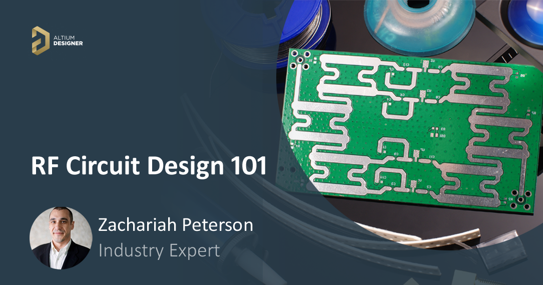
Digital systems designers are likely familiar with some RF components and routing styles, but there is much more that goes into RF circuit design. An RF circuit can include integrated circuits, discrete semiconductors, and printed RF elements that work together to produce required functionality. RF circuit design involves combining all of these elements to build an entire system and create a PCB layout.
RF circuits are non as intuitive as typical circuit diagrams, and sometimes a diagram may appear to violate basic electrical design rules. However, due to the propagating nature of the electromagnetic field, circuits running at RF frequencies act very differently from typical integrated circuits operating at DC or in digital bands. Whether you’re designing a system for wireless communication or just need to design a transmission line with specific impedance, pay attention to these basics of microwave engineering.
- Introduction to RF Circuit Design
- Planning Your Board Construction>
- Common RF Circuit Designs
- Tools for RF Circuit Design and Layout
It’s often joked that radio frequency (RF) design for integrated circuits and PCBs is something you only need to know to pass your qualifying exams in university. However, many of today’s specialized products will need to work with a mixed signal component, incorporate a wireless communication block, or will support a high frequency application like radar. RF design is now coming back into the mainstream, and designers who aren’t familiar with RF design should read this guide to brush up on their skills.
Introduction to RF Circuit Design
RF circuits are designed to mimic the standard circuit elements and some simple integrated circuits by constructing structures using printed elements on a circuit board. RF circuits can appear a bit foreign as they do not always use off-the-shelf components. Instead, RF circuits can use printed traces on a PCB and some additional components to provide desired functionality in a circuit board.
Printed RF Circuits
Printed sections of an RF circuit board will use copper traces to build circuit elements. The arrangements of traces, capacitor or inductor elements, and semiconductors in an RF circuit may appear un-intuitive, but they take advantage of propagation behavior in the electromagnetic field to produce the desired electrical behavior. There are some important conceptual points to remember about RF circuit design, as well as how RF circuits on a PCB will behave electrically:
- Passivity: All printed RF circuits are passive unless an active off-the-shelf component is added to the design. However, there is research into active RF components built entirely from printed traces.
- Linearity: RF circuits constructed from printed traces are always linear, meaning the voltage and current are related by a linear function (straight line on a graph). These circuits only become nonlinear if a nonlinear semiconducting component is added to the circuit, such as a diode.
- Propagation: All RF circuits take advantage of wave propagation. This means input impedances need to be used when determining how to match impedances around a circuit and how to create interfaces between different sections of an RF circuit.
- Signal integrity: RF signal integrity relies on electromagnetic shielding and isolation as RF signals need to be as noise-free as possible. Many unique shielding structures and layout techniques have been devised to help provide the required shielding and isolation in RF systems.
Active RF Circuits
Active RF circuits can include anything from an oscillator to driven amplifiers, ADCs, and transceivers. These components can be used in addition to printed traces to provide additional functionality. Many radar modules, wireless systems, amplifiers, and telecom components will use active components alongside passive circuits to route RF signals and provide required signal propagation behavior. Signal sampling, manipulation, and processing is performed with active components, which can also provide an interface back to digital systems.
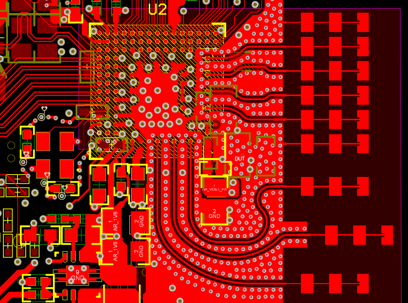
Planning Your Board Construction
Just like a high-speed digital PCB, successful RF circuit design relies on building a PCB stackup that can support your RF circuits. The stackup should be designed so that RF elements have the desired characteristic impedance, although the impedance of your system will be a much more complex function of your RF circuit layout and routing. In addition, the relevant frequency at which your board operates will determine how the stackup should be built, what types of printed circuits you might need, and what RF components you can use. RFIC design follows many of the same ideas as in RF PCB design, and a mastery of these concepts will help you succeed in any area of RF design.
RF PCB Materials
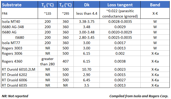
FR4 materials are acceptable for RF transmission lines and interconnects operating up to WiFi frequencies (~6 GHz). Beyond these frequencies, RF engineers recommend using alternative materials to support RF signal propagation and printed RF circuit designs. Standard FR4 laminates use resin-filled fiberglass weaves to hold components, but these fiber weave effects in certain materials could create signal and power integrity problems if fabrication procedures are not specified properly.
Alternative material systems use PTFE-based laminates and bondply materials to bond a PTFE layer with the next layer in your PCB stackup. These materials have lower loss tangent than FR4 materials, so signals can travel farther without attenuating and still fall within acceptable margins. These laminates should form the substrate that supports RF transmission lines at very high frequencies, such as 77 GHz radar, or for very long interconnects at lower frequencies, such as 6 GHz WiFi. The table below summarizes some important material properties for common RF PCB materials.
PCB Stackups with RF Materials
Once you’ve selected your laminate and bondply materials for your RF design, it’s time to add them to your stackup. While you could build an entire multilayer PCB stackup with RF materials, it’s generally not needed and can be overly expensive. One option is to build a hybrid stackup, where the RF laminate is placed on a top layer to support RF transmission lines and circuits, and the internal layer is used to support ground planes, routing for digital signals, and power. The opposite layer can also support digital components that need to interface with your RF front end, any ADCs for collecting RF signals, or other components.
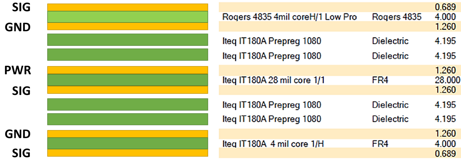
If you don’t need a digital section in your RF PCB layout, you can go with a 2-layer or 3-layer PCB with RF laminates that have standard or near-standard thickness. Once you’ve determined the PCB layer thickness and material system, you’ll need to determine the impedance of your RF traces.
Calculate RF Trace Impedance
After the stackup is determined, you need to calculate the width of conductors on the PCB to produce a desired impedance in your RF circuits (normally 50 Ohms). The impedance of a trace and its dimensions are related using some formulas that are derived with a technique called conformal mapping. Currently, the best resource for finding formulas to calculate trace impedance with complex dielectric constant is Brian C. Waddell’s Transmission Line Design Handbook. However, these formulas cannot be solved for specific widths, so a numerical technique is needed to determine the width required for a transmission line to have a specific impedance.
- Learn more about calculating microstrip impedance
- Learn more about calculating symmetric stripline impedance
For a more complex arrangement, such as offset striplines or waveguides, a better option is to use a stackup design tool with an integrated field solver. These utilities can account for copper roughness, tapering during fabrication, differential routing arrangements, and the location of the traces between layers. They are also easy to use inside your PCB design software.
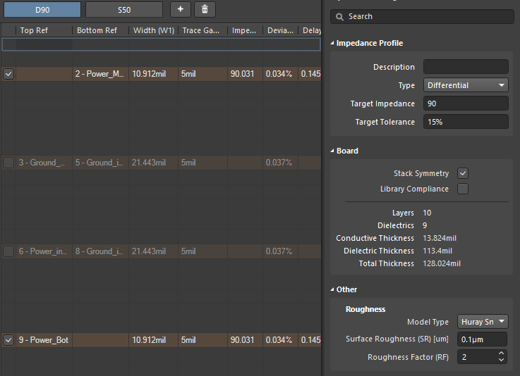
Once you know the impedance of your interconnects, you’ll still need to determine impedance matching requirements, either by looking at reflection simulation results or by looking in datasheets. For transmission lines used in printed RF circuits, the input impedance of different transmission line sections is used to determine impedance matching for a given circuit. If you’re interfacing transmission lines and components in RF circuits, you’ll need to include the input impedance when designing and impedance matching network for RF components.
- Learn more about transmission line impedance values
- Learn more about the critical length in a transmission line
Common RF Circuit Designs
It’s important to design your PCB stackup before you design your RF circuits, especially passive RF circuits, because they will require specific impedance targets to be reached to function properly. In addition, printed RF circuits take advantage of electromagnetic field propagation on transmission lines, and the propagation behavior will depend on the dielectric function of the substrate material. Once these details are worked out, you can begin designing your RF circuits and select additional components for your system.
Printed RF circuits are designed by calculating transmission line sections for use in specific structures on a PCB. Your transmission line designs will guide propagating waves to components while also providing behavior like attenuation, amplification, filtering, resonance, and emission (e.g., as an antenna). Impedance transformation at stubs, interfaces with components, and antennas is often needed to overcome impedance mismatch seen by an RF signal as it propagates. The various printed structures that produce these functions are well-known in many textbooks.
Some structures and components used in RF circuits and PCBs include:
- Passive and active filters
- Attenuators
- Circulators
- Amplifiers
- RF power splitter, divider, and combiner
- Antennas
- Resonators
- Waveguide cavities
Once you add in your other components, you’ll need to create schematics of your circuits before you can start your layout. The process for placing RF circuits in a schematic is the same as that used for digital systems. Circuit simulations are also important in front-end RF engineering as you’ll need to evaluate the electrical functionality of your system before you create your PCB layout. This is normally performed using SPICE simulation in your design with printed elements in your board defined as transmission line objects in SPICE. The best schematic editors will include transmission line objects to allow you to accurately simulate electromagnetic behavior in your circuit board.
Tools for RF Circuit Layout
Once your RF circuit design is finished and has been put through circuit simulation tools in your required frequency range, it’s ready for physical layout. RF PCB designers often need to take a mechanical approach to carefully design their RF interconnects while also obeying standard high frequency design rules, such as minimizing vias and trace lengths. Any high frequency circuit that will appear on a PCB needs to be designed to meet impedance targets and geometric tolerances, so your CAD tools need to interface with your electrical design rules to ensure compliance to these objectives.
If you also have digital components that must interface with your RF circuits, they need to be placed in a PCB layout using the same set of tools. Careful placement and proper stackup design will help prevent interference that corrupts high frequency circuits and RF signal collection. Native 3D design tools can be helpful here as well because some RF systems are multiboard systems, and the overall assembly needs to be inspected before preparing for manufacturing.
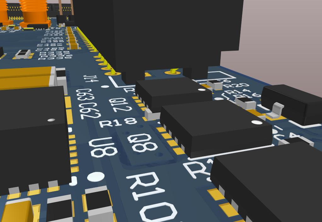
When you need to build advanced RF systems that also maintain signal integrity, you need a complete set of circuit simulation tools, PCB routing and layout tools, and a layer stack design tool to help you reach impedance targets. Whether you need to layout a low noise amplifier for signal collection, RF power amplifier for broadcasting signals, or complex interconnects with unique trace and via structures, the best PCB layout tools will help you stay flexible as you create your RF PCB layout.
Circuit designers, layout engineers, and SI/PI engineers trust the advanced design tools in Altium Designer® for RF circuit design and physical layout. When a design is finished and ready to be released to manufacturing, the Altium 365™ platform makes it easy to collaborate and share your projects.
We have only scratched the surface of what’s possible with Altium Designer on Altium 365. Start your free trial of Altium Designer + Altium 365 today.
