Serial Communications Protocols - CAN and LIN
In this article, we will be looking at the popular CAN and LIN protocols together. This article is part of the series Serial Communication Protocols. We hope this resource will prove invaluable on the next occasion when you find yourself implementing a serial communication bus as part of your design. We aim to help you choose the best option for your circumstances.
CAN Bus
CAN stands for Controller Area Network and is a communication protocol used by various electronic devices. CAN is often used to provide communications between devices in vehicles, like engine management systems, active suspension, ABS, gear shift control, lighting control, air conditioning, airbags, central locking system, and other systems found in a vehicle.
CAN is a high integrity serial data communication bus ideal for real-time applications. The bus can operate at data rates of up to 1 Mbps and has excellent error detection and correction capabilities. CAN was developed by Bosh with its primary application being for automotive applications, but it is now also in many industrial automation and control applications.
CAN is a multi-master, message-based protocol. This means that all the CAN devices can transmit data, and several CAN devices can request the use of the bus simultaneously. CAN network has no addressing system and instead uses a prioritized message system. All the messages are divided into a range of priorities.
There are several versions of CAN bus in use today, which include:
- CAN 2.0A – Uses an 11-bit Message Identifier
- CAN 2.0B - Uses a 29-bit Message Identifier
- CAN FD - Uses a Flexible Data Rate
In a CAN bus, a transmitting device sends a message to all the CAN nodes, and each node decides how to react to the received message. Also, the nodes determine each message’s priority if several messages are sent at the same time.
There are three different speed types for CAN buses, which are:
- Low Speed - 125 kbps data rate and 500 meters maximum bus length
- High Speed (or Hi-Speed) - 1 Mbps data rate and 40 meters maximum bus length
- Flexible Data Rate - 15 Mbps data rate and 10 meters maximum bus length
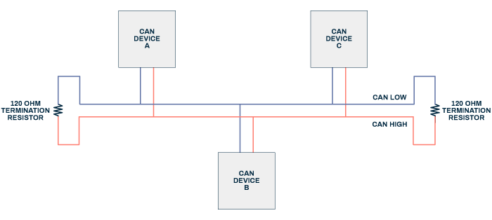
CAN bus uses differential transmission lines and therefore does not require a ground connection. 120 Ω termination resistors are used at each end of the differential lines, as shown in the circuit diagram below.
A differential pair transmission line is much more robust and immune from environmental interference and noise. This is because the two signal wires are kept very close to each other, so when the electromagnetic interference affects one transmission line, it will equally affect the other. Because there is no reference ground in a differential pair, the CAN bus voltage is measured from the difference between the paired differential transmission lines.
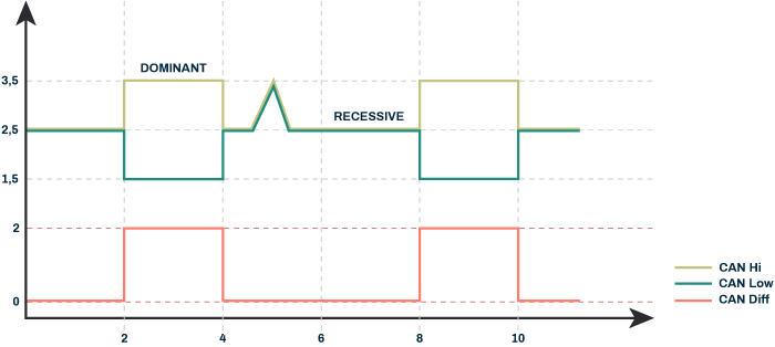
In the CAN differential transmission lines, the dominant logic level is low or 0, while the recessive logic level is high or 1.
Below is a complete CAN protocol frame for a standard 11-bit message:
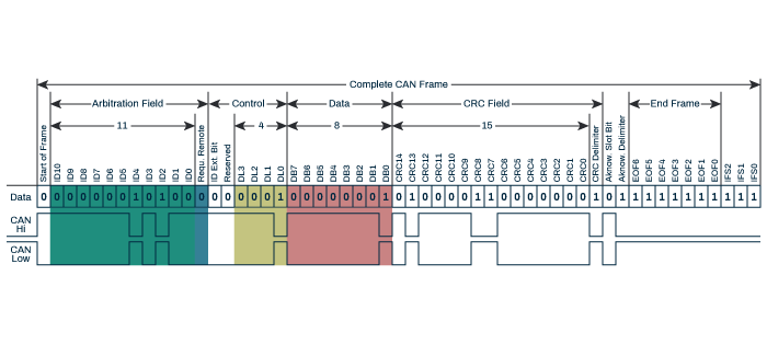
The message begins with the Start Frame, which indicates the start of the message. Usually, the CAN bus will be in an idle state (1), so to identify the beginning of the message, the dominant 0 signal is sent, which wins over recessive 1.
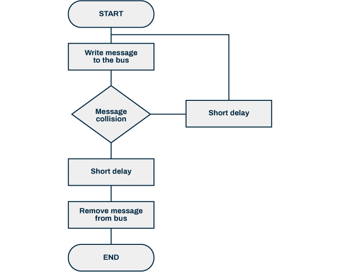
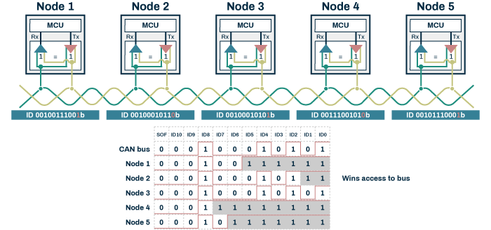
This is followed by the Arbitration Field, which indicates the priority of the data. The transmitters identify a message priority when they start to send a message. If multiple transmitters send a message simultaneously, they detect this when they detect they are sending recessive logic level 1 but the actual Arbitration Field bit on the bus is a dominant level 0. This tells the affected transmitter to delay transmitting, as it is not the highest priority. This continues until only one transmitter is left to send its message. Once this message has been sent, the other lower priority transmitters restart the process. This repeats until all the messages have been sent in the order of priority, as shown below:
The next bit is the Remote Transmission Request. This bit shows what the format of the message frame will be. It can be a Data Frame, which is used when the transmitter sends information and is indicated by being set to the dominant logical 0. Alternatively, it can be a Remote Frame, where the transmitter requests information and is denoted by being set to the recessive logical 1.
The next bit is the ID extension. If the ID extension is set to the dominant logical 0, then the Arbitration field will be a standard 11 bits in length, which is sufficient for 2048 different identifications. If this bit is set to the recessive level 1, then the Arbitration field will be extended 29 bits in length, which is sufficient for 536870912 different identifications. The additional 18 bits of the Arbitration field following the ID extension bit.
The next bit is reserved, and it usually is set to a dominant logic level 0 but setting to the recessive logic level 1 will have no effect.
The next four bits are the Data Length Code bits, which show how many bits will be in the data field. The data length can vary from 1 to 8 bytes, equating to between 8 to 64 bits.
The next 15 bits are the CRC (Cyclic Redundancy Check) field used for error detection.
The next bit is the CRC Delimiter, which must be set to the recessive logic 1.
The next bit is the Acknowledgement Slot Bit. The transmitter sets this to the recessive logic level 1. If the message is received successfully, the receiver indicates this by overriding this bit and assigning it to the dominant logic level 0.
The next bit is the Acknowledgement Delimiter, which must be set to a recessive logic 1.
The last seven bits are the End of Frame indication, which identifies that the message has ended.
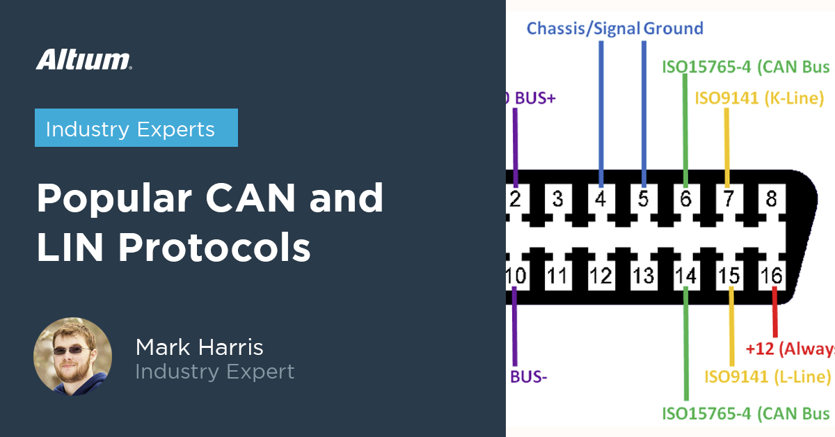
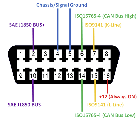
The standard OBD2 automobile connector includes the CAN Bus differential pair pins for use for diagnosis or software control purposes:
https://components101.com/connectors/obd2
LIN Bus
LIN stands for Local Interconnect Network and is an electronic communication protocol primarily used in vehicles similar to CAN. The LIN protocol’s need arose because buses using the CAN protocol become too expensive when every device in a car is needed to communicate via the bus. Because of that, European car manufacturers began to use a different serial communications system, which led to compatibility problems.
LIN was created by five automakers: BMW, Volkswagen Group, Audi, Volvo Cars, and Mercedes-Benz, with the help of Volcano Automotive Group and Motorola.
The LIN communication network is a master-slave arrangement. Typically, the LIN bus consists of 16 nodes (1 master and 15 slaves). All the LIN bus messages are initiated by the single master. At the same time, only one slave may respond at any time to a message chosen using an identifier sent by the master.
Data is transferred between the devices connected to the LIN bus using fixed form messages of variable length. The master device transmits a break signal followed by synchronization and identifier fields to initiate data transfer. The slave devices can reply by sending a data frame that contains either 2, 4, or 8 bytes of data plus 3 bytes of control information.
LIN may be used as a sub-bus connected to a CAN bus. The CAN bus sends a signal to one of its nodes, which can itself be a LIN master. When the LIN physical layer transmitter receives the message, it converts it at a logic level to the LIN protocol using the CAN battery voltage level (typically 12 V). The LIN transmitter also includes a current-limited wave-shaping driver, which reduces electromagnetic emissions.
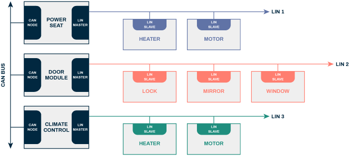
The LIN slave receivers then convert the high battery level voltage data from the LIN bus into lower voltage level logic signals that can be sent to a microcontroller.
LIN operates as a serial broadcasting system using a one-wire bus with a ground reference. Typical LIN bus speeds are relatively low compared to CAN or other serial communication protocols (<20 kbps). However, the cost of implementing the LIN bus is significantly reduced, making it ideal for mass production. It is mostly used for less critical non-safety functions. LIN is often used for controlling windows, air conditioning, wipers, etc. The maximum length of a LIN bus is 40 meters.
On the LIN bus, signals can be either dominant (logic level low or 0) or recessive (logic level high or 1).
The LIN protocol uses message frame structures that follow one of six frame types as listed below:
- Unconditional Frame – this is the message frame that all the subscribers (slaves) receive (assuming no errors were detected)
- Event-Triggered Frame - this message frame increases the responsiveness of the LIN cluster (LIN cluster - one LIN data bus) without using excessive bus bandwidth
- Sporadic Frame - this message frame is transmitted when required to prevent a collision with other messages
- Diagnostic Frame - this message frame carries diagnostic or configuration data and always contain eight bits
- User-defined Frame - this message frame can carry any type of information
- Reserved Frame – this message frame is reserved for confirming LIN networks and should not be used in LIN 2.0
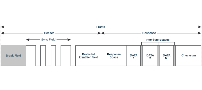
LIN buses have become very popular in the last decade because of their standard protocol, simplicity, and low cost, with more than 600 million LIN nodes fitted in automobiles in 2020.
LIN is now also being used in applications in non-automotive industries such as home appliances and industrial automation.
Summary
This article has looked at some features of the popular CAN and LIN protocols and discussed some of their advantages and implementation details. In the other articles in this series, we will look at some of the alternate serial communication protocols available.
If you want to know more, why not browse our product page for a more in-depth feature description or call an expert at Altium.