CAN-Bus: The Protocol

This article is part of a three-part introductory series on the controller area network bus, better known as CAN bus:
- Part 1: An Informal Introduction
- Part 2: The Protocol
- Part 3: Designing CAN-bus circuitry
Introduction
In the first article about the CAN bus, we looked at the physical layer and the different hardware standards, such as HS-CAN and low-speed fault-tolerant CAN. If you have yet to read it, you can find it here.
The most important concept we must keep in mind to understand the higher-level layers of CAN bus is recessive and dominant bits. The raw bitstream differs from most other digital buses that simply use two different voltage levels to code 1's and 0's. The bus is driven dominant, while it defaults recessive thanks to the termination resistors when it’s not driven actively. In other words, dominant bits are 0's, and recessive bits are 1's.
While the physical layer may be responsible for electromagnetic interference (EMI) rejection and the general “sturdiness” of the standard, the protocol is responsible for the features that truly differentiate the CAN bus from the competition, such as non-destructive arbitration and collision detection.
The CAN Bus Protocol
The CAN bus protocol is best suited for short, broadcast messages of 8 bytes maximum that are not directed at any specific node, but instead shouted by a node to the whole network.
The website kvaser.com, one of the leading providers of CAN bus hardware and software, summarize it as follows:
“Hello everyone, here’s some data labeled X, hope you like it!”
And they’re spot on!
That label is the identifier, and it’s the beating heart of the CAN bus protocol. The identifier is an 11-bit field in the standard CAN bus protocol and a 29 bit field in extended CAN protocol.
Their Majesty, The (11-bit) Identifier
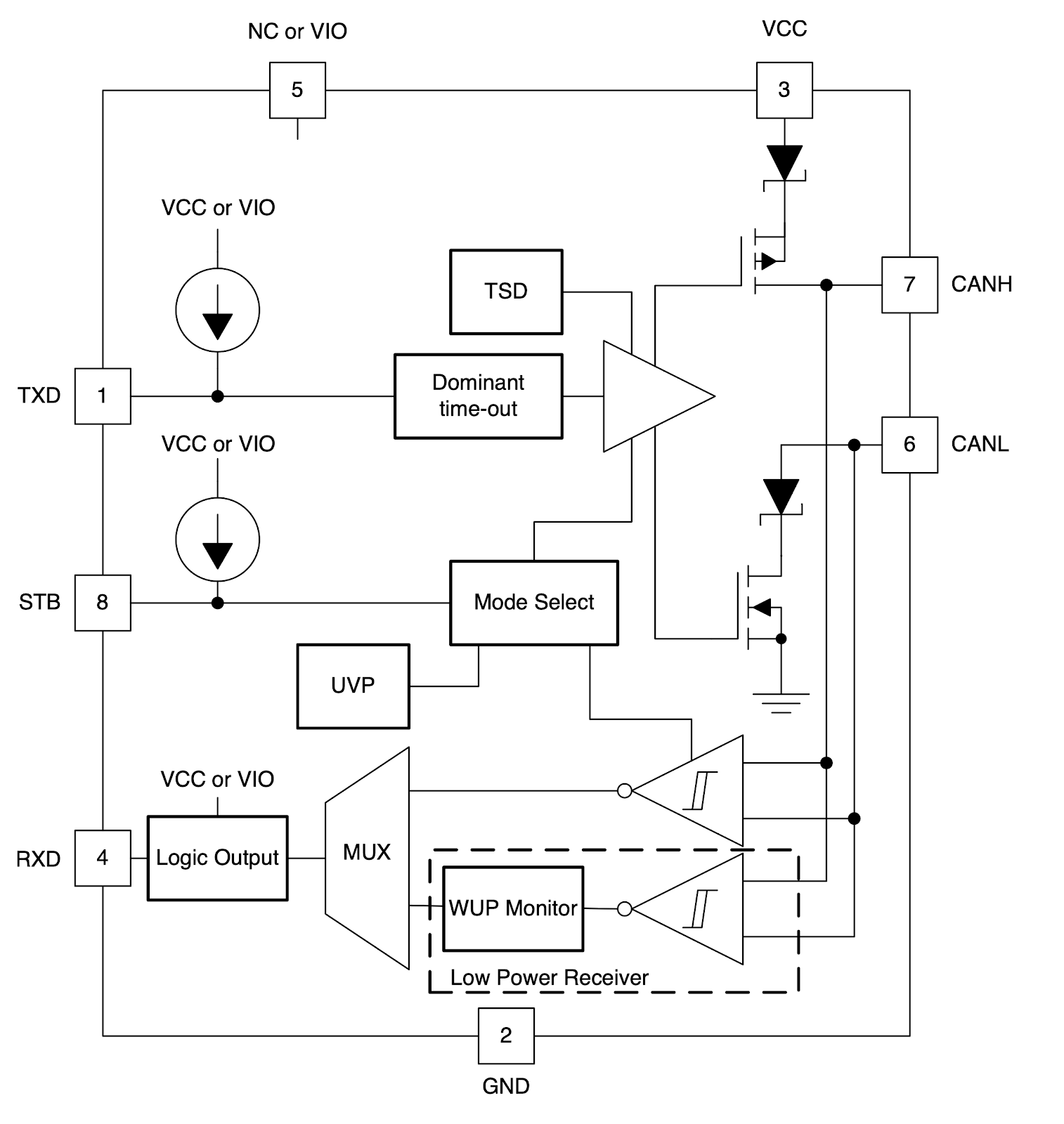
Given that every node shares the same communication line, there must be some way of arbitrating who can speak and who should stay silent. In CAN bus, every node is always listening, including the node which is transmitting. This mode of operation can be observed in the transceivers' internal schematics, such as the following from TI, where input and output circuits are wired together:

The messages with higher priority are those with a lower-value identifier. Assuming two nodes try to transmit 0b0100000 (node A) and 0b0110000 (node B) at the same time, the following happens:
- (bit 6) A and B drive the bus to dominant. They listen, and the bus is dominant. Everything is going according to plan.
- (bit 5) A and B don’t drive the bus, remaining in recessive state. They listen, and the bus is recessive. Everything is going according to plan.
- (bit 4) A drives the bus recessive and listen: everything all-right! B doesn’t drive the bus, as the bit is supposed to be recessive. But the bus is being driven by A. B will not shut up, as A won the arbitration. B will be able to send an error message to warn there was a collision next time around.
- (bit 3–0) Rinse and repeat.
The arbitration is non-destructive, as the node who wins it continue transmission without impairment. The system works the same with a 29-bit identifier, although there are a couple of bits in the middle as it’s split in two fields of 11-bit and 18-bits, respectively.
The Standard CAN Bus Frame
Now that we have discussed how the physical layer (in the first article) and arbitration work, we can take a look at the bits of a standard CAN bus message with an 11-bit identifier.
- SOF: Start Of Frame. Like most protocols, CAN bus starts with a cute little bit; in this case, a dominant bit. The leading edge is also used to synchronize the nodes.
- Identifier: as discussed, this is the identifier. You can note it’s at the start of the frame, so it’s always clear what node has the right to speak during communication.
- RTR: remote transmission request. Dominant when the message is used to request information from another node instead of asserting it. “Hey, bro, tell me something about X".
- IDE: identifier extension. If this bit is dominant, the frame is a standard CAN bus message with an 11-bit identifier.
- r0: reserved bit for future amendments.
- DLC: 4-bit data length code counts the number of bytes being transmitted.
- Data: the sweet, sweet data being transferred.
- CRC: 15 bit of good-old cyclic redundancy check.
- CRC delimiter: One recessive bit of padding.
- ACK: This bit is very peculiar. Every receiving node overwrites the recessive ACK bit with a dominant bit, thus acknowledging the reception (if the CRC is correct) by at least one node. If any node had issues reading the message, they must send an error frame the next time around.
- ACK delimiter: one recessive bit of padding.
- EOF: End-of-frame, a sequence of seven recessive bits.
The good news is, you don’t have to take care of any of these. CAN bus controllers are incredibly sophisticated devices and automatically handle the whole network protocol, error communication, CRC, and the like. They are operated at a high-level, usually by just specifying identifier, data, and eventual filters for the incoming frames.
Things to Watch for - Data Field Length
The max length of the data field in a CAN bus frame is 64 bits or 8 Bytes. The 8 bytes makes dealing with standard binary formats such as 32 and 64 bit floats much easier than in competing formats like Modbus, where you can only access 16-bit region of memory one at a time.
At the same time, 8 bytes are not infinite, and we can quickly run out when trying to transfer strings of binary data; as We’ll see, higher layer protocols such as CANopen take care of that.
Things to Watch for - Bit Stuffing
CAN adopts a technique called bit-stuffing. After five consecutive bits of the same logic state, a bit of opposite level is stuffed into the bit-stream. The bit stuffing happens only between a SOF (Start Of Frame) and the seven recessive bits that define the EOF and is an integral part of how CAN bus hardware does automatic fault detection. If you see the same values too many times, something is broken!
When debugging, random bits can be extremely frustrating, so keep this in mind when using an oscilloscope or a logic analyzer.
Things to watch for - it takes two to tango
For a CAN bus frame to be valid, the frame must be acknowledged by overwriting a recessive ACK with a dominant one. The smallest possible CAN bus network thus requires two nodes. To simplify development, I recommend using a well-tested commercial development board as a second node.
Higher-Level Standards - CANopen
Suppose you need a way for your nodes to “assert” information of up to 8 bytes with a priority-coded identifier. In that case, you don’t need anything higher level than the CAN bus protocol itself.
This approach is similar to how the CAN bus protocol operates in many vehicular networks: a node shouts the gas pedal position, and everybody reads it. You can cleverly subdivide the identifiers, so they are easy to mask using the features most CAN bus controllers provide or by writing custom firmware.
There are some performance caveats: if you’re not smart about how you use the identifiers and need messages delivered on-time, you can end up with a bandwidth one-third the nominal one.
Since the CAN bus bus physical layer and network protocols are almost as good as chocolate mousse, several higher-layer protocols have been created. The most popular protocol that is not closed behind a high wall of NDAs and one-sided agreements is CANopen.
Object Dictionary
The object dictionary is a data structure containing a series of entries, a bit like a database table with a field “data” that can be of almost any binary type.
There are a few entries that must be defined, like error registries and a heartbeat, but the rest is optional. Since the index of the dictionary is 16-bit, there are a lot of possible entries.
Each entry has the following attributes:
- Index: 16-bit index
- Object name: a string that describes the entry
- Size: single record or array
- Type: datatype of entry. Float, integer, array, etc.
- read/write, read-only or write-only
- Mandatory/Optional field
Services
The CAN-open services are the means to access the object dictionary, control the network and the nodes. If the object dictionary is data, services are actions to be performed.
PDO and SDO
The SDO (Service Data Object) service allows us to read and write data inside the object dictionary of remote notes in a client/server fashion. It can read/write data of arbitrary length and all supported data types, but uses a confirmation frame for every data frame, in addition to using 4 bytes of the 8 bytes available to manage the communication, and has thus a considerable overhead.
The PDO (Process Data Object) service enables to stream data with a broadcast message in pretty much the same exact way the CAN bus bus was conceived to do. PDO is the service to use, for example, to stream sensor readings.
Differently from SDO, the PDO service can transfer multiple object dictionary entries at once, as long as you can squeeze them into 8 bytes. Every PDO has it’s own entry in the object dictionary as well. Since every node can read the object dictionary, for example, when the network is set up at the boot-up time, every node can look up how the data inside a PDO message is organised.
PDOs can be used asynchronously, for example, to send a message when a new sensor reading happens, or synchronously, when a SYNC frame is received. A series of sophisticated timers allows us to automate this task and avoid flooding the network with multiple messages.
NMT
The NMT (Network Management) protocols are used to start and stop the nodes, detect when the nodes boot up (and thus join the network), and if they are ready for operation or error conditions occur.
Heartbeat
The Heartbeat protocol operates by communicating in a producer/subscriber fashion: one node subscribes to another's heartbeat, which will periodically send “I’m still alive!” messages.
Similar to the heartbeat protocol, node guarding is available to check a slave node when working in master/slave operation, and lifeguarding when the slave wants to check on the master.
Timestamp
The timestamp protocol allows synchronising the clocks of multiple nodes down to the microsecond level. Conceptually it’s similar to the NTP protocol used by every modern computer, but all nodes can be synchronised at once thanks to the broadcast nature of the CAN bus.
Sync
The Sync protocol enables multiple nodes to perform one action at the same time. For example, a master device can setup multiple slaves to read their sensors when a sync message is received, then transmit the sync frame to trigger the action.
Emergency
A node experiencing a fatal error can send an emergency message complete with custom error codes and other data. The emergency frame has a higher priority than standard frames.
Electronic Data Sheet
The EDS (Electronic Data Sheet) is a standardised file format that describes the behaviour of CANopen devices. Many EDS editors allow exporting extensive documentation of the object dictionary and template C code to speed up development.
The EDS is required to pass CANopen certification.
The EDS can be used to tag and enrich CANopen network traffic with metadata and make debugging the network more manageable.
How to Manage Auxiliary Documentation (the Unadulterated Sales Pitch)
The CAN bus protocol can be… A LOT!
I want to share with you a little trick I use all the time to keep supporting documentation synced through Altium Concord Pro™ on Altium 365®. The first step is converting any web page into PDF files that can be more easily managed.
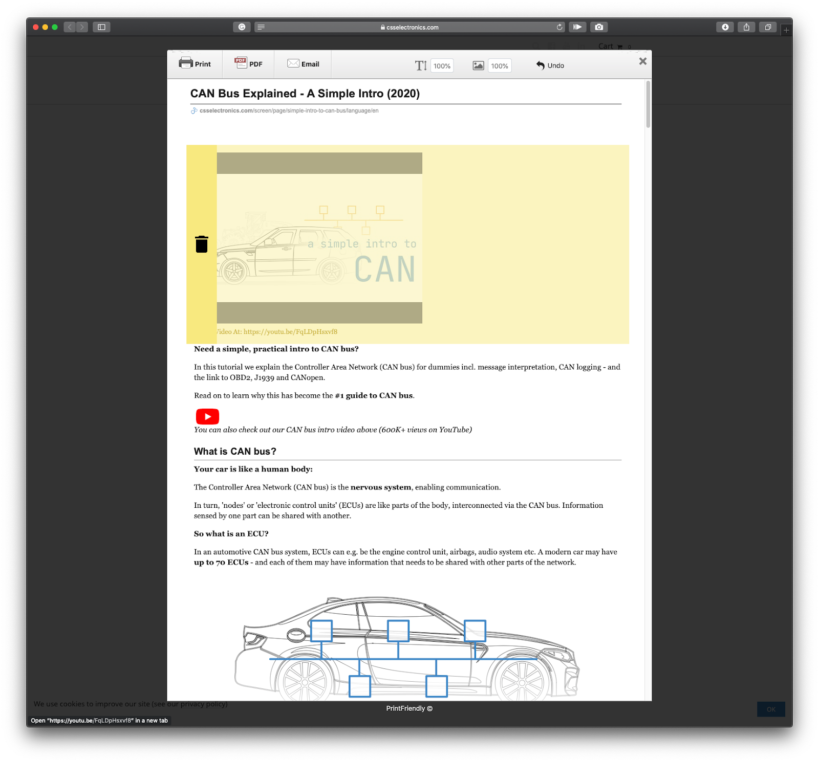
I lost count of all the solutions I tried in the past years to achieve this, but I’ve settled on a browser extension called PrintFriendly. It’s available on all major browsers and can be used through a simple javascript bookmark, thus being compatible with Android, iOS, and iPadOS devices as well.
In this example, I am converting “CAN Bus Explained - A Simple Intro,” a tutorial by CSS electronics that far outweighs mine in both technical depth and readability. Any excess content, such as author bio or advertising, can be easily removed.

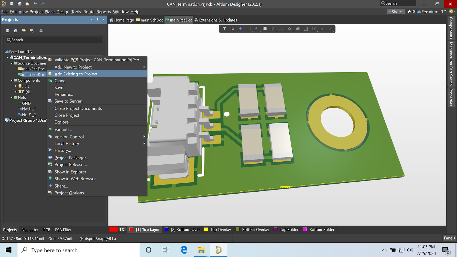
The docs can be added added to project files through the “Add Existing to Project” command. Since the version control is based on GIT, it’s crucial all project documents reside under the same root folder; otherwise, they can’t be added into the repository.

When saving to the server, the new documents are automatically selected during the commit process and can be found in the project tree.
.png)
By keeping all your documentation together with your projects, you will have easy access to it through Altium Designer® and will be able to take full advantage of Altium 365 sharing capabilities and Concord Pro project synchronization features. Once your documentation is saved within your project folder, it’s revision-controlled and distributed together with your project files, reducing the risk of discrepancies.
Further Resources
CAN Code:
CAN Documentation:
- Can-Bus explained by CSS Electronics
- Texas Instruments SLLA270, “Controller Area Network Physical Layer Requirements”
- Microchip AN228, “A CAN Physical Layer Discussion”
- Analog Devices AN-1123, “Controller Area Network (CAN) Implementation Guide”
- Wolfhard Lawrenz, CAN System Engineering, Springer, ISBN: 978–1–4471–5613–0
- Steve Corrigan (Kvaser), “Minimum distance between CAN nodes”
- Texas Instruments SLLA279A, “Critical Spacing of CAN Bus Connections”
CANopen Documentation:
CANopen Code:
- CANopenNode C Library
- CANopenSocket Linux library
- Python library
- libedssharp Object dictionary editor
CANopen Software:
- CANopen Magic (commercial)
- CANopen Architect (Commercial)
- Caneds free object dictionary editor
- Linux Can-utils
Conclusion
The CAN bus features a sturdy, reliable physical layer and a protocol of rare elegance that enables collision-detection and non-destructive arbitration. This has fueled the standard’s ever-growing popularity. Projects that use CAN bus are likely to require extensive documentation. With Altium Concord Pro, you can leverage all the power of GIT to ensure your documentation is placed in version control, and you can easily share it with your colleagues and collaborators through the Altium 365 platform. Talk to an Altium expert today to learn more.
