Testing the Limits of Your LDO's Efficiency

If you’re designing a circuit board to be powered by anything except a bench-top regulated power supply, you’ll need to select a power regulator to place on your board. Just like any other component, your regulator has stated operating specs you’ll see in a product summary, and it has more detailed specs you’ll find in a datasheet. The fine details in your datasheets are easy to overlook, but they are the major factors that determine how your component will interact with the rest of your system.
Power regulators like LDOs are simple to place and use in your design. They are literally plug and play, with the simplest fixed-output LDOs requiring 3 terminals and a few external resistors to use properly. LDO efficiency can’t be guaranteed to sit at a specific value, but this value is related to the current limit your board can access during operation. Before you wire up a high voltage input to an LDO, make sure you read these guideline to ensure you can supply enough power.
What Determines LDO Efficiency?
LDOs are simple and operate with the same principle: the component steps down an input voltage to the desired output, and the excess electrical energy is dissipated as heat. LDOs are externally adjustable with a voltage divider, and you’ll need some input/output caps for additional filtering. Every LDO has a simple equation that determines the efficiency:

When the input is close to the output voltage, the efficiency is close to 100%. Note that this equation only applies when the voltage differential (output - input) is above the dropout voltage level (typically less than 1 V at low current, and as much as 1.5 V at high current). As long as you’re in this state, the LDO will properly regulate the input to produce a low-noise, low-ripple output. The simplest LDOs will output a fixed value, or the output can be adjusted as needed with external resistors. Since the output voltage is fixed to some value, increasing the input voltage will not continue increasing the output, so the efficiency decreases.
So what’s the problem with the above points? Where does the efficiency suddenly degrade? To see this we have to look at the output voltage and current. At high input voltage differential, there is a drop off in efficiency and power output.
Output Voltage and Current
There is an important specification that you should look at in your LDO datasheet: the short circuit current. This is effectively the largest current the device can supply, and this value will vary with input voltage differential. Remember, the output voltage and current are fixed and will not increase if the input voltage is increased, so best practices dictate the input should be slightly above the output voltage value. This is why you normally see LDOs used for small step-downs, such as 5 V to 3.3 V for known current requirements.
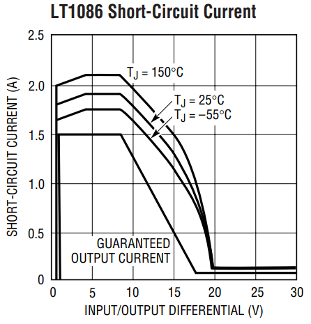
There is one other point that is important when considering the short-circuit current and voltage differential. The short-circuit current will also decrease when the LDO is driven with a very high voltage differential. This is rather important because some LDOs, such as an LDO with 3.3 V output, will have input voltage allowance as high as 30 V. At high input voltage differential, the short-circuit current will drop off and become limited, which will limit the total power output.
The example below shows the short-circuit current vs. input differential curve for LT1086CM from Linear.

This component has a range of possible outputs with a high limit on input voltage. If you’re running at high input (above 20 V voltage differential), the component won’t source more than about 100 mA. This needs to be considered when selecting a regulations strategy for your board, as well as determining potential temperature rise.
Heat and Temperature Rise
Since the lost power is dissipated as heat, this should also be considered in your design. The lost power in an LDO is equal to:

Again, when the input and output voltages are close together, the power loss is minimal, but running at high differential with a few amps of output current can lead to overheating and failure.
Just an example, a typical junction-to-ambient thermal resistance value for an LDO is about 25 deg-C/W. it's possible the LDO burns out and fails. Let’s look at the above example with the LT1086 driven with a voltage differential of 25 V for a load demanding 1.5 A. Due to the current limit at high input, heat is generated at a rate of about 2.5 W in this case, equating to a case temperature rise of about 62.5 Celsius. If you were operating near the top end of the low input range with a voltage differential of only 8 V at 1.5 A, you would dissipate about 12 W, giving about 300 Celsius temperature rise. The latter case will cause the component to fail.
The Verdict: LDOs Are Great If Used Correctly
If you’re using an LDO, make sure to stay within the right operating limits to ensure the device works as you intend. If you don’t mind generating a lot of heat and operating at low current, then feel free to run your LDO at high input voltage with a large voltage differential. Just be prepared to accept very low efficiency in that arrangement. If instead you operate the device within an intended input range, which you can see from a few graphs in the datasheet, you’ll have the highest possible efficiency with low dropout and high available current.
One good arrangement is to have a switching regulator as your primary regulator with the output connected to an LDO. Switching regulators are nice because they use reactive circuits to modulate the output power instead of a resistive element, but this creates switching noise seen at the output. However, using the LDO provides additional regulation up to ~100 kHz frequencies.

The other option is to just transform your line voltage directly down to a value just above your dropout voltage. Unfortunately, with real components, you’re not able to just transform down to any value you want, you’ll have to use an off-the-shelf component with a specific turns ratio. Getting down to the specific input voltage you need for an LDO might require a custom transformer, so keep this in mind before you try regulating the line voltage for use with an LDO.
Once you’ve created your components and designed a power circuit for maximum LDO efficiency, you can create your new design in CircuitMaker. Users can create multi-sheet schematics for projects with multiple power regulation sections as needed, and CircuitMaker makes it easy to transition your design into a new PCB layout. All CircuitMaker users also have access to a personal workspace on the Altium 365 platform, where they can upload and store design data in the cloud, and easily view projects via a web browser in a secure platform.
Start using CircuitMaker today and stay tuned for the new CircuitMaker Pro from Altium.
