How to Speed Up Your DFM Report Process in the Cloud

Experienced fabricators will tell you: any design could have some hidden DFM problem that will interfere with manufacturability, quality, or yield. Making use of your design rules is just the start of preventing DFM problems, you’ll want to collaborate with your manufacturer throughout the design process if you want to spot and correct DFM problems.
Within Altium Designer, there are multiple reports you can generate for your projects that will help you summarize important information on your board for a client or a manufacturer. When my team is working on backplane projects or networking equipment designs, we often use the Net Status report to summarize lengths for critical nets, and these can be cross-checked against important signal integrity rules.
If you’re preparing a new design for manufacturing, the Altium 365 platform allows your team to share your validation reports as part of your project releases. This is a great way to easily share important design data with your manufacturer, customers, or other designers as you prepare your board for manufacturing. The version control and Project Release features in Altium 365 let you send your reports directly to the shop floor while also tracking changes to your design, documentation, and project releases over time.
Using Validation and DFM Reports in Altium 365
The Board Report feature in Altium Designer is an excellent way for a designer or a manufacturer to summarize information on a PCB layout and check this against their capabilities. Some manufacturers prefer to develop their own reports, sometimes with external software packages that scan through Gerber files. With this feature, you or your manufacturer can quickly summarize important board information before finalizing a design for manufacturing.
To access this feature, click on Board Information in the Reports menu with the PCB editor open. When this window opens, you’ll see a list of options that can be automatically generated from your PCB layout. In the example below, I’m using a modified version of Mark Harris’ sub-1 GHz radio transceiver project as an example.
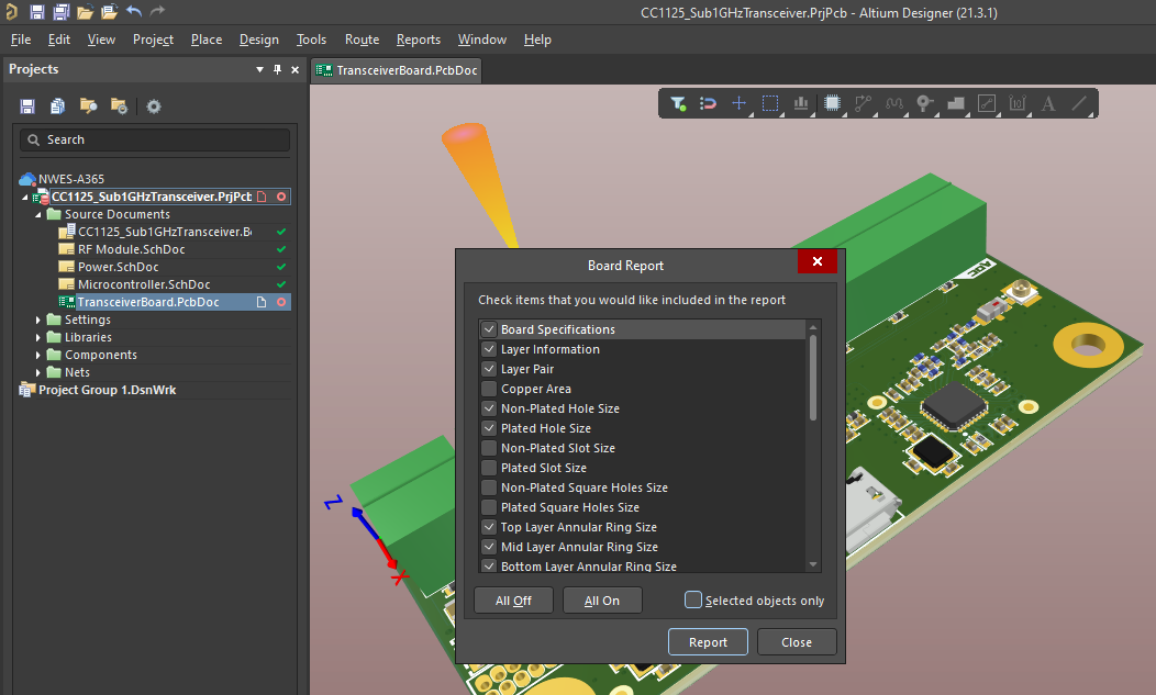
There’s a lot you can generate from this feature, but your fabricator won’t need all of it. There are some major points here that any fabricator will look at to ensure manufacturability:
- Annular ring sizes, particularly if you’re aiming for IPC Class 2 or Class 3 compliance
- Minimum feature sizes, particularly via hole sizes and trace widths
- Clearances between different objects in the board
- Solder mask expansion on pads
The above list contains some minimum aspects of DFM that apply to just about any circuit board. However, more specialized boards or components may carry specific requirements in any of the above areas to ensure high quality during fabrication and assembly. If you plan to use this feature to collaborate with your manufacturing partner, talk to them and ask for their DFM requirements, they’ll tell you what information they look at to assess manufacturability.
Where’s My Board Information Report?
The report you generate won’t be automatically added to your project, but it will be created in the project folder on your local disk. The report exists as a text file and an HTML file; you will need to include both files in your project. Make sure to add it to your project; once it’s in your project you can add it to version control in Altium 365. This means each time the project is changed and a new report is generated, Altium 365 will track these changes throughout the history of the project.
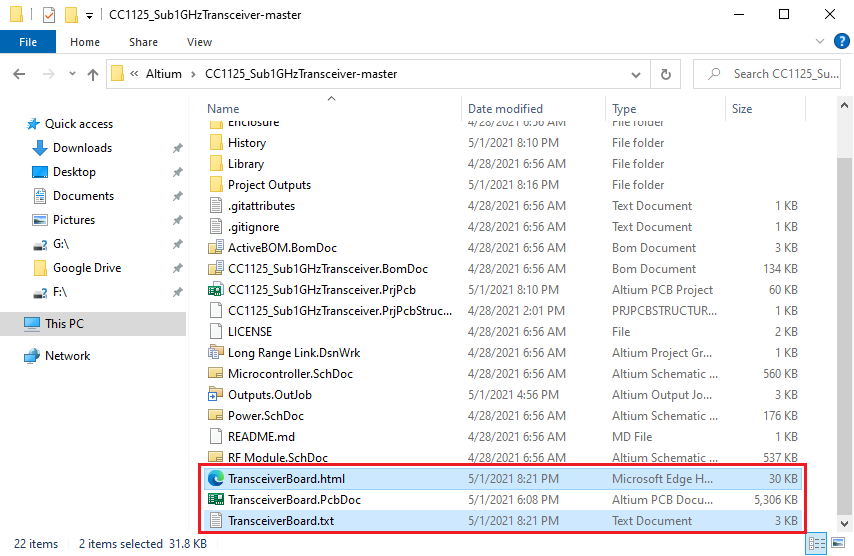
Process for Using Board Information Reports
Here’s one process you can follow when using the Board Report feature as a DFM report:
- Generate the required Board Information report for your project. You’ll generally want to focus on the areas in the above list so that your fabricator can quickly scan through your board information and spot any DFM violations.
- Navigate to the project folder on your local disk. Use the Add Existing to Project feature to add both files into your project. They will appear in the Projects Panel.
- Once the text and HTML files are added into the project, save the project to your Altium 365 Workspace.
- Share the project data with your manufacturer.
Just like any of the steps you need to follow for design and project management, there is no set method to use any of the project data you generate in Altium Designer. However, when planning for manufacturing, it’s important to get some kind of DFM report in front of your manufacturer before you finalize the design. The above process is a great way to do this as it gives your manufacturer everything needed to quickly compare your board with their capabilities. This also applies to complex designs with thousands of nets and components.
How you complete Step 4 above is your choice, and you’ll have several options available through your Altium 365 Workspace. These options for sharing your board information as a DFM report are convenient as they can be used with any manufacturer, even manufacturers who don’t use Altium Designer.
How to Share the Board Report With Your Manufacturer
Probably the simplest way to do this is to invite your manufacturer to your Workspace. Even if you add your manufacturer as a team member, you can still limit what they can see within your workspace to only their allowed projects. This way, if your manufacturer is an Altium Designer user, they can open the project in Altium Designer and view the board report directly. There are some other options your manufacturer can use if they don’t have an Altium license.
Download a Snapshot From the Project History
One quick way a manufacturer can get access to the board report is through the Project History feature in your Altium 365 Workspace. From here, the manufacturer can download the board report and run their own DFM checks without opening up the project files. To get access to the board report, just navigate to the Project History area and download a snapshot of the project.
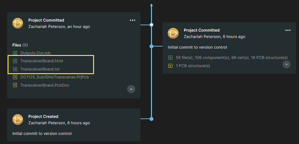
If all your manufacturer needs to do is open up the board report, then this is a quick and easy option. Once the files are downloaded, the board report can be viewed by opening up the HTML file in the file package. This not only helps your manufacturer identify design choices that violate their capabilities, it also helps them quote your board as they can see via sizes and via counts. This is also a quick way to start the quotation process before the design is finalized and fabrication files are generated.
If there are any problems found in the board report, your manufacturer could send an email outlining the required changes. A better option is to go to the Design area in the 365 Workspace via the web browser and leave a comment directly in the project files. This is preferable because the comment history will be saved and trackable along with the rest of the design data.
Project Packager and Project Releaser
Two other sharing options we’ve discussed in the past are the Project Packager feature and the Project Releaser feature. The Project Packager would be used by the designer within Altium Designer to create a ZIP file with all the project files. This could then be emailed directly to your manufacturer, or it could be shared through a proprietary file sharing system, FTP portal, or a typical cloud solution like Google Drive.
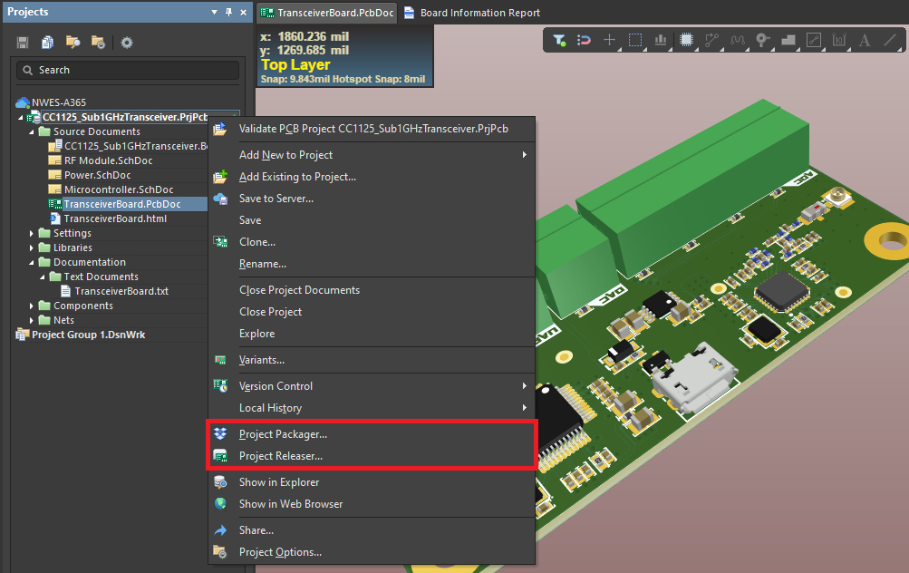
The Project Release feature is preferable if you’re like me and you want to cut down on all the back-and-forth emailing that tends to happen on complex PCB projects. Once a Project Release is created, you can go into your 365 Workspace and use the Send to Manufacturer feature to give them access to the entire set of project files. This is a great option as the manufacturer doesn’t need to be added to your workspace, and you don’t create any risks that any sensitive project data gets exposed to an unauthorized party.
Fixing Common Clearance Problems
One of the most common DFM error I’ve encountered in projects is clearance errors. These are usually hole-to-copper (antipad diameter), pad-to-copper, or trace-to-copper clearances, and often for specific nets like power and ground. Thankfully, it only takes a couple minutes to fix these problems in Altium Designer by modifying the design rules and repouring your polygons. Using the Board Report feature as the start for your DFM report process lets you and your manufacturer instantly spot these clearance problems just by reading through a list.
Instantly Generate Gerbers After Inspecting the Board Report
If everything in the DFM report looks good, you or your manufacturer can immediately generate Gerbers directly in the 365 Workspace through the web browser. Simply open up the Design section of the project, and on the right side of the screen, you can open up the Download area. From here, your manufacturer can generate Gerber files for the project.
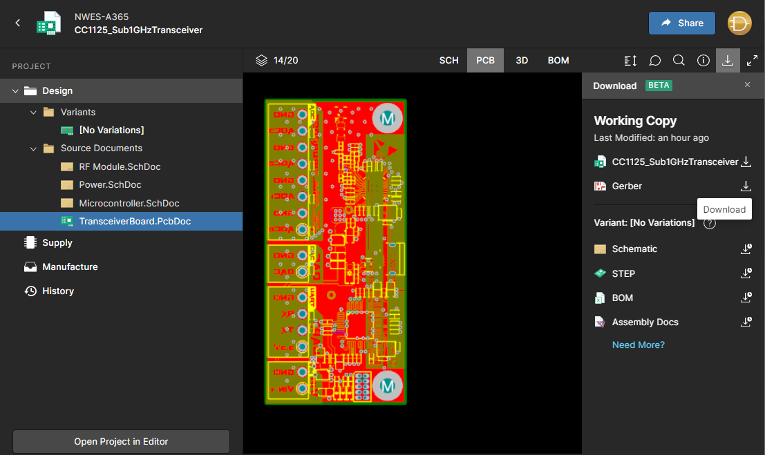
The person who generates the files from the web browser will receive a download link once the files have finished generating. This is extremely convenient for a collaborator who doesn’t have an Altium Designer license as they can download all the important documentation they’ll need without creating an Outjob file.
The list of tiles that can be generated through a web browser isn’t limited to Gerber files. Notice along the right-hand side of the screen, there are several files you can create without using Altium Designer. You’ll have more customizability for any deliverables if they are opened and created in Altium Designer, while Altium 365 only generates a standard set of files.
However, this does give a manufacturer a quick and easy way to get the board to the next stage of a DFM check and run some more DFM analysis. This is often done with specialized CAM software or proprietary software, and the manufacturer will eventually need the Gerber files to complete these final checks. If everything checks out, they can instantly put the board into fabrication.
The Altium 365™ platform gives you, your team, and your manufacturer the tools you need to quickly get your board through DFM report checks and help you move immediately into fabrication. You’ll have all the tools you need to share, store, and manage all of your PCB design data in a secure cloud platform. Altium 365 is the only cloud collaboration platform specifically for PCB design and manufacturing, and all the features in Altium 365 integrate with the world-class design tools in Altium Designer®.
We have only scratched the surface of what is possible to do with Altium Designer on Altium 365. You can check the product page for a more in-depth feature description or one of the On-Demand Webinars.
