Using a Thermal Camera for PCB Diagnostics
There has likely been a time when you’ve powered on a freshly built prototype for the first time, only to find you’ve hit the current limit on the lab power supply. Even as you increase the current limit to way beyond what you would expect your board to draw, the lab power supply is still limited. If it’s safe, you poke around the board with your finger, but you can’t feel any parts that are hot to the touch. Also, probing around with a multimeter doesn’t identify any short circuits, unexpectedly low resistances, or significant voltage drops. So, what can you do next to track down where the problem is on your new prototype? If you’ve spotted this article’s title, you’ve probably already guessed that the answer is to use a thermal camera.
Unlike the clumsy human finger, a thermal camera can detect minute temperature differences across its view. This allows you to rapidly identify any components that are consuming current. Any parts or areas of your board that draw current will also generate heat that can easily be picked up by a thermal camera.
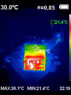
As an example, below is a thermal image of an isolated regulator drawing over 100 mA at 5 V. In the top right corner of the image, we can see a current limiting resistor and a LED. The LED is drawing just 5.2 mA and still can be easily identified against the background of the colder board, along with the track that is supplying current to it.
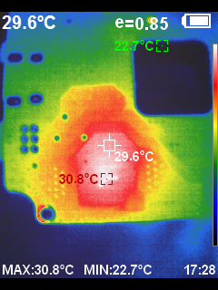
Using a thermal camera, we can also see how well heat is transferred to the other layers. For example, below is a thermal image of the circuit board’s bottom side with a voltage regulator shown above. After several minutes of run time, you can clearly see the heat that has been absorbed by the board and the copper polygons’ shape.
A thermal camera also provides benefits once your board is up and running, allowing you to closely monitor a power device, such as the switched-mode regulator shown below, with a relatively large inductor. It’s a nice feature that you can clearly see the difference in emissivity between the black epoxy body of the inductor and the white text printed on it in the image below.
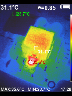
Looking at the image above, we can clearly see that the regulator IC also has a temperature gradient across it.
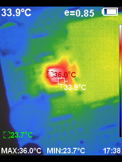
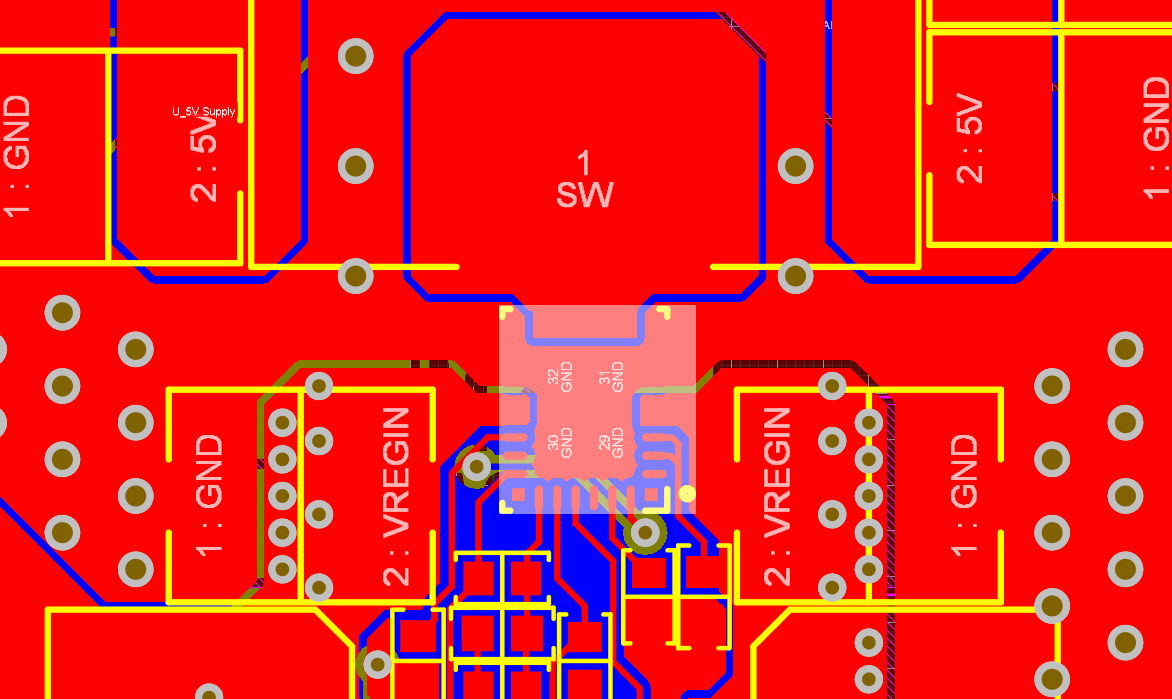
Above is a thermal image of the regulator from another angle that shows a 2 oC temperature difference across the regulator IC. This is because the IC’s right-hand section has significantly more copper connectivity to large copper pours than the left-hand side, as seen in the image below.
DIY Close Focus Lens
One problem with many of the thermal cameras in the lower echelons of the price range is that they have a fixed focus. These fixed-focused thermal optics struggle to work with objects that are very close to the lens, such as a PCB. They are typically intended more for building inspection applications than for examining objects just a few inches/cm away.
A member of my Altium community has reported that they use a cheap laser cutter lens as a focusing element on their camera, and it works well. So, I thought I would try this technique using my relatively low-cost camera. I already had a laser cutter and some spare lenses, so it was a very simple test to undertake. My camera isn’t quite as easy to mate with an extra lens compared to theirs. However, using a bit of masking tape quickly allowed me to try out the idea, and it worked wonders, giving me a temporary mount until I can figure out something more permanent.
Laser cutter lenses are available in a range of diameters and focal lengths. The correct lens diameter is relatively simple; it just needs to be the same width as the camera lens. The focal length comes from how far the lens needs to be from the object to achieve focus. I’m using a 2” focal length lens for all the pictures in this article, but a 3” or 4” lens would give you a better overview of the entire board. 1.5” lenses are also common and would allow you to look very closely at a particular section of your board if you need to look at the heat generated by individual small passive components. This will be perfect if you are working with 0402 or smaller components.
Things to Watch Out For
While thermal cameras are absolutely fantastic diagnostic tools, they can only be used to look at an emissive material rather than one that is reflective to long-wave infrared.
Most metals, glass, and very high gloss materials can reflect infrared light. To get the most accurate readings from your thermal camera, you will need to spray-paint your entire board matt black as this will give the whole board a consistent emissivity. Solder joints, aluminum capacitors, metal leads, and metal connector shielding will all reflect infrared light at almost perfect levels. This means you will only get a temperature reading for the heat bouncing off the object. If I only need to do a quick reading for debugging purposes, I will cover the most prominent metal objects on my board with masking tape. The masking tape will still get hot and emit infrared energy for the thermal camera to pick up, and it is easily removed afterward. You could also vacuum bag your board using a flexible bagging film such as Stretchlon or use a peelable solder mask on the board, depending on your specific requirements.
Would you like to find out more about how Altium Designer® can help you with your next PCB design? Talk to an expert at Altium.