Three Ways To Simplify Output Generation Using Altium Designer
Download the PDF to keep learning offline
Many of the delays involved with the PCB design to Manufacturing process can be avoided with accurate data and documented notes for fabrication and assembly. In addition, easily reproducing the required data can be a huge time saver for communication between PCB designer and fabricator. The Output Job Configuration file available in Altium Designer can provide a suitable solution for controlling and ultimately simplifying the output generation of a PCB design.
TOPICS IN THIS SOLUTION
WHY SIMPLIFY THE OUTPUTS GENERATION PROCESS?
You’ve completed an exhausting PCB design. The project is done, right? Not at all; it simply is an intermediate point before the product enters fabrication and assembly into the final product. Handing the design to manufacturing can be a significant part of the project itself, organizing and assembling the set of files that must be provided to the manufacturer for fabrication and assembly.The typical files required are the Bill of Materials (BOM), Gerber files, NC drill files, ODB++ design iles, IPC-2581 files, pick and place step files, and assembly drawings.
Other items may be added to or removed from this list, depending on the fabrication and assembly requirements. It’s also not uncommon for the board fabrication house to request new data or additional data from the PCB designer after initial submission.That’s why it’s important to establish a consistent workflow, so that it is easy to locate, organize, and assemble the required documentation.Standardizing on a particular flow, or at least having a standard starting point for datageneration facilitates a less painful post-design process. This paper presents three ways that will improve the way you prepare a design for manufacturing handoff, making it quicker and eliminating error sources.
THE PCB CYCLE
At the conclusion of a PCB design process, the designer creates a set of files to be communicated to the board fabricator. This is a multi- step process that can take up valuable time, especially if this process has to be replicated for each new revision or modification. Manufacturing documentation can become a significant pain point, plus the number of files needed for fabrication and assembly, introduces the risk of error.
The figure, below, shows the typical PCB manufacturing cycle, beginning at the top and moving clockwise.
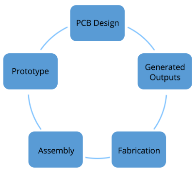
Basic PCB design-to-manufacturing cycle
Once the fabrication house received the incoming data files, they analyze them to first determine if all the necessary data has been delivered. If they don’t have all the information they need to produce the board, they will request new data, more data, or revised data from the board designer. Once the new or revised data is requested, the board designer will have to go through their initial process of generating each desired file. The extra time that this reproduction takes, heavily depends on the particular process or flow the PCB designer uses for output generation. Each iteration can hamper overall productivity because of the time and money that is lost for each repeated step.
The flow between PCB designer and fabricator must be as seamless as possible, as this communication is critical to producing a correct, functional board within the shortest time possible. Here are three ways to use PCB design software to make your handoff to manufacturing much more efficient and to eliminate error sources.
STANDARDIZE OUTPUTS
Altium Designer provides tools and automation to produce and control all data and documents for fabrication and assembly. These tools make the job much less painful and helps assure that no errors are introduced.
An Output Job Configuration file (*.Outjob) can be added to any project and becomes the one source where all required outputs can be generated. Output file types include Netlist, documentation, assembly, fabrication, report, validation, and export outputs.You can setup an Output Job Configuration file that has all the required outputs ready for generation. In the figure below, this standard Outjob has been configured to include several outputs. It is shown in a ready status to generate a Pick and Place file, a Test Point Report, a set of Gerber files, a set of NC Drill files, and a BOM. Any other required files can be added or removed as desired.
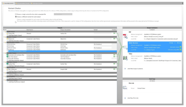
Standard Output Job file
SET AN OUTPUT LOCATION
Set up a specific location to save all generated outputs. The location can be either on a shared network drive for ease of transfer or a local drive. In the figure below, the generated files are being saved to the local disk drive. Regardless of where the files are saved, you have complete control of the location and what files are included.
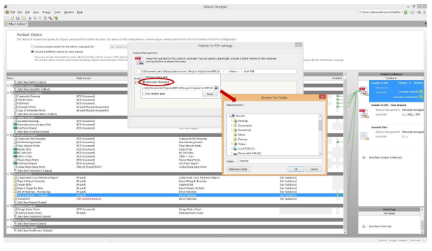
Specify a location to save the output files
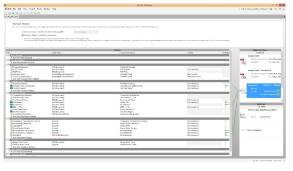
Data source for Outjob
REUSE OUTJOB CONFIGURATIONS
One of the best features of the Outjob file is the ability to reuse it for multiple projects. The data source for a given output can be set as a reusable source. For example, in the next figure, the data source for the assembly drawings was set to “PCB Document” as opposed to the specific project name “SL1 Xilinx Spartan…” Not only can the board designer quickly generate or regenerate the desired files, but the designer can also quickly generate or regenerate the same standard files for a new project.
