Spotting DDR4 Impedance Violations in High Speed PCB Design

High speed interfaces can be difficult to layout and route without the right set of design and analysis tools. Protocols like Ethernet, USB, DDR, MIPI, and others require precise single-ended and differential impedance control in your PCB layout. This, in turn, requires designing a stackup for controlled impedance routing with defined trace geometry and return path. It’s no wonder some designers have a hard time getting started with high speed layout and routing.
Once you have completed your layout and routing, the question of whether your routing is correct comes up. Online DRCs certainly help you stay within your design constraints and prevent routing mistakes that can compromise impedance, create excess crosstalk, and create EMI susceptibility. When you do have a problem like an impedance variation, it can be difficult to spot and correct without the right field solver.
Altium Designer® already gives PCB designers a set of world-class layout and routing features, and it integrates directly with the field solver utilities in the Ansys SIwave® package. The combined capabilities of these tools gives designers access to multiple integrated field solvers for running signal integrity, power integrity, and EMI analyses directly from PCB layout data. Let’s look at how these tools can be used to identify DDR4 impedance variations and what can cause these impedance variations.

Why Impedance Variations Matter
In a previous blog post, we looked at the Mini PC example project that comes prepackaged with Altium Designer. We located an EMI problem in the DDR4 section of the board using the hybrid solver in SIwave, which was related to the power plane impedance in the board, specifically the PLL_1V8 net (Layer 6). In addition to running DRCs, there are other important signal integrity metrics that should be checked in the layout before signoff. Some examples are:
- Impedance variations on any impedance-controlled nets
- Return paths for high speed signals
- Crosstalk between high speed nets
- S, Y, and Z-parameter extraction on critical nets
- Parasitic extraction on critical nets
Impedance variations on specific nets can be hard to spot during the layout phase. Although you can define an impedance profile for specific net classes and easily route traces with controlled impedance in Altium Designer, the impedance seen by signals on a trace can change as you work through the layout. After modifying the shape of planes and copper pour regions, you might make a layout decision that modifies the impedance on critical nets. Similarly, while finishing the layout for a complex board, it’s possible a designer puts a discontinuity in the return path for a critical signal. For this reason, it’s important to use some verification tools in addition to the DRC engine built into Altium Designer.
After your layout is finished in Altium Designer, you can spot impedance variations in a trace with the field solvers in Ansys SIwave. The Ansys EDB Exporter extension in Altium Designer allows you to easily interface with SIwave and run simulations directly from your PCB layout data. Here, we’ll focus on DDR4 nets in the Mini PC layout in Altium Designer, and the Impedance Scanner tool will be used to catch any impedance variations along DDR4 nets.
DDR4 Impedance Targets
The Mini PC board contains two onboard 8 GB DDR4 DRAM chips running at 1866 MHz, and routing between the FPGA and DDR4 chips needs to be impedance controlled. For the Micron MT40A512M16LY-107E DRAM modules used in this board, selectable on-die termination allows 34/40/48 Ohm single-ended impedance or 85/90/95 Ohm differential impedance (other values are available as well).
Upon an initial survey of the Mini PC board, we can see some DDR4 nets (symmetric striplines in byte lane 1, Layer 7) that cross below a split between the PLL_1V8 power plane and a GND plane (Layer 6). The lower half of these nets is referenced to the VDD_DDR plane (Layer 8), which powers the DDR4 modules and is adjacent to a ground plane (Layer 9). The specific nets in byte lane 1 are shown below in Figure 1.
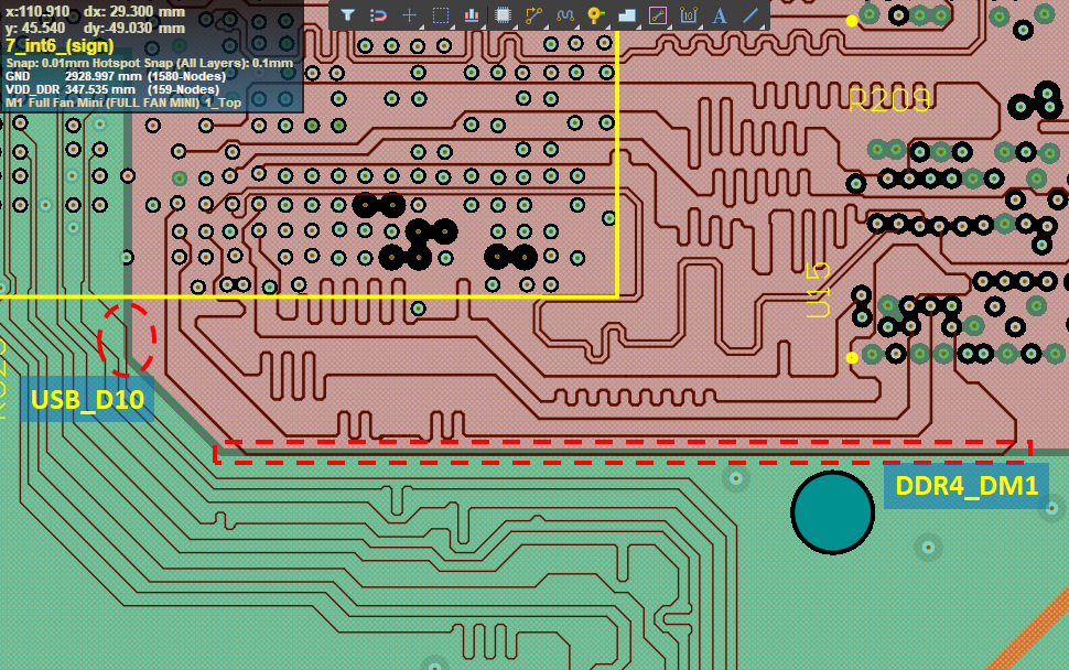
Here, we see two nets crossing beneath a split in the PLL_1V8 plane and GND, one of which is DDR4_DM1 (part of the DDR4 bytelane 1). Compared to the USB_D10 net, DDR4_DM1 has a very long section that passes between the split between PLL_1V8 and GND. The section of DDR4_DM1 that crosses between the two planes is very long, and it is possible the impedance of this section of the trace differs significantly from the desired impedance.
Here, the Simberian field solver in Altium Designer shows that the single-ended impedance for these stripline traces was designed to ~42 Ohms (0.15 mm width, Dk = 3.6, 0.24 mm between Layers 6 and 8). This design assumes the planes above and below the stripline are uniform, which would provide the required impedance in this geometry. Due to the gap between the planes, the stripline appears asymmetric and one would expect to see higher impedance in this section. The impedance throughout the DDR4 section can be quickly examined using the field solver in the Impedance Scanner tool in Ansys SIwave.
Impedance Scanner Results
The field solver results from the Impedance Scanner are shown in Figure 2. This figure shows the characteristic impedance of each net routed to the onboard DDR4 modules. The inset panel shows a magnified view of the DDR4_DM1 net. The impedance is shown visually using a heat map, allowing the impedance of specific sections of the trace to be identified and compared with the DDR4 impedance target defined above.
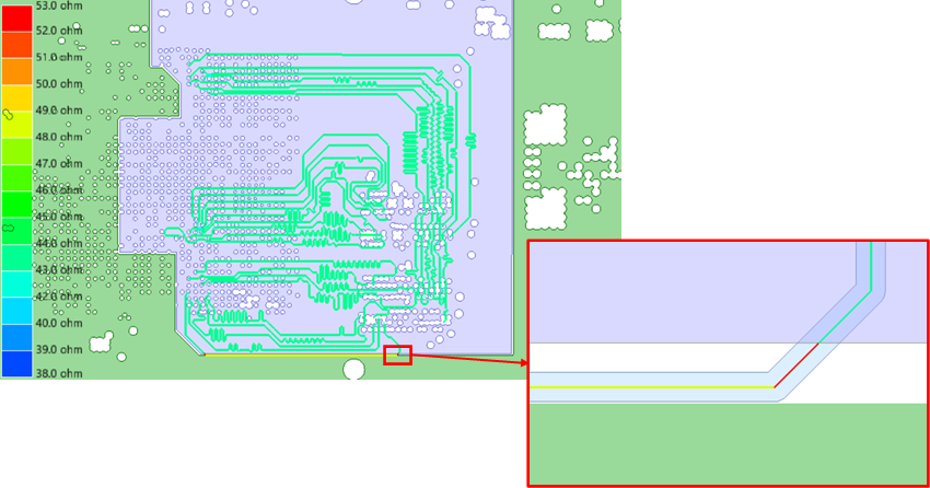
From the above results, we see the extent of the impedance deviation in the long straight section of the trace, as well as the angled section leading back below the PLL_1V8 plane. The field solver returns a single-ended impedance of ~44.5 Ohms for the single-ended DDR4 nets in Figure 2. In the long section, we see the field solver returns an impedance of ~49 Ohms, which puts the impedance just at the edge of the +/-10% tolerance spec under the JEDEC standard. The shorter section is seriously out of spec as its impedance is ~53 Ohms.
Possible Solutions
The stackup in this board already creates difficulties with creating a consistent return path for high speed signals as return currents are induced into the PLL_1V8 power plane, which does not have an adjacent ground plane. In terms of a distributed circuit model, this decreases the per-unit-length capacitance of the stripline arrangement, which produces the larger impedance seen in the simulation results. In addition, the routing is already dense and spacing between these nets needs to be maintained to reduce crosstalk.
The possible solutions to these problems in the layout include the following:
- Change the layer stackup so that these DDR nets reference a continuous ground plane on Layer 6.
- Try to modify the routing near the bottom edge of the PLL_1V8 plane so that DDR4_DM1 sits beneath PLL_1V8.
- Modify the span of the PLL_1V8 plane so that it overlaps DDR4_DM1.
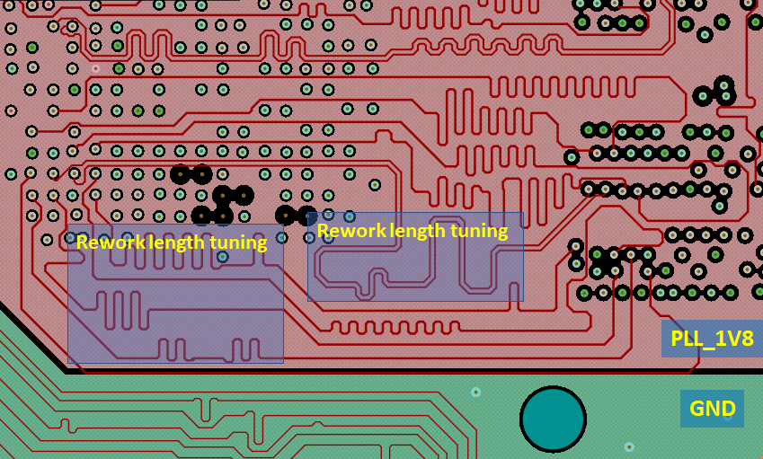
The best solution that will not conflict with the recommendations given in the previous blog post is a combination of points #2 and #3. One option is to rework the length tuning sections shown in Figure 3 in order to make room for DDR4_DM1.
Summary
After identifying possible DDR4 impedance violations in Altium Designer’s Mini PC example project, the impedance of the DDR4 nets was visualized using the Impedance Scanner in Ansys SIwave. This allowed us to identify a specific section of the DDR4_DM1 net with impedance that falls out of spec. Some practical solutions can be quickly implemented with the interactive routing features in Altium Designer, and the design could again be simulated with SIwave as needed.
Register for the join Altium and Ansys webinar to learn more.
Thanks to the Ansys EDB Exporter extension in Altium Designer®, PCB designers can run signal integrity and power integrity simulations using Ansys SIwave®. This simulation package takes data directly from your PCB layout, giving designers access to multiple 3D field solvers for time domain or frequency domain simulations and analyses.
