Complete Power Supply Filter Design and Simulation Guide
Zachariah Peterson
| Created: June 29, 2021
A PCB for a power supply can be as difficult to design as high-speed networking equipment and complex embedded systems. These circuit board designs need to account for a range of behaviors and safety requirements, especially when dealing with high voltages and currents reaching the output of the power supply. In addition to safety standards involved in power supply PCBs, component selection is critical for ensuring the design can provide the desired power output without excessive noise, ringing, and heat generation.
With the right CAD tools and component sourcing features, it’s easy to find and add components to your power supply designs. You can then quickly create your layout while ensuring your design complies with basic industry standards on ESD, current and thermal management, safety and much more. Keep reading to see some important guidelines on power supply PCB design and how you can ensure
ALTIUM DESIGNER®
The industry’s best electronics design and simulation application for professional power supply designers.
Filters are an extremely important circuit with a simple function: remove some frequency content from a desired electrical signal. As a noise removal and power conditioning element in a power supply, the filters that are used in power supplies are normally low-pass filters designed to pass DC current to a load. These filters could also be chokes that remove common-mode noise from the input or output lines of a power supply. Because these are so important, power electronics designers need simulation and layout tools to help them design, evaluate, and construct filters for power supplies.
Filter circuits are fundamental for controlling noise in any electronics system, but even simple filter circuits need to be evaluated for functionality. Some of the basic tools power systems engineers need for filter design are:
- A circuit design and schematic creation utility for selecting filter components and building filter designs
- An integrated SPICE simulation package for evaluating electrical functionality
- Integrated schematic capture functions to import PCB footprints into a blank circuit board layout
- Component sourcing features to help find parts and procurement data for major distributors
With this complete toolset in Altium Designer, power supply filter design is much easier and only takes a single application. Follow these guidelines for power supply filter design to ensure your designs will have low noise and desired power output.
Any filter design proceeds by considering the specific type of noise that needs to be removed from the system. Power supply designs need to consider 4 general types of noise that should be removed with a filter circuit. These noise sources and the filter topology used to eliminate them are summarized in the image below:
Noise source | Filter strategy |
Broadband conducted EMI from input power lines | Low-pass filter and common-mode choke on the input |
Conducted EMI reaching the output stage and passed to the load | Low-pass filter and common-mode choke on the output |
Switching noise from the PWM signal | Low-pass filter on the output |
Radiated EMI from specific noise sources | May require a bandpass filter in extreme cases |
From the above table, we see that power supply filtering generally involves a low-pass filter to remove differential-mode noise and a common-mode choke to remove common-mode noise. The specific topology involved is generally an LC circuit, but the differential-mode filters could be an active filter with an op-amp in cases where feedback loops with gain are needed.
Integrated SPICE Simulations for Your Power Supply Filter Design
Any filter will need to pass multiple simulations to ensure it provides the desired bandwidth, rolloff, attenuation, and number of poles. A frequency sweep and transfer function are the primary tools used to evaluate power supply filters. However, the power output should also be examined to ensure the filter will not reduce DC power, thus power supply filters are often LC circuits with zero resistance. Your power supply filter topology can be thoroughly simulated when you have an integrated SPICE package in your circuit and schematic design tools.

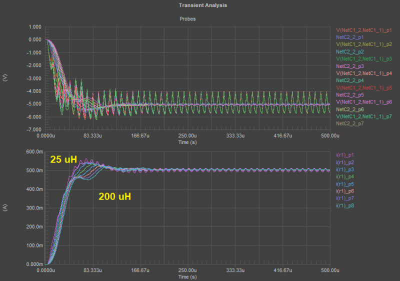
Altium Designer includes a powerful SPICE simulator with parameter sweep features. You can perform important design tasks like determining the right inductor size for a switching regulator.
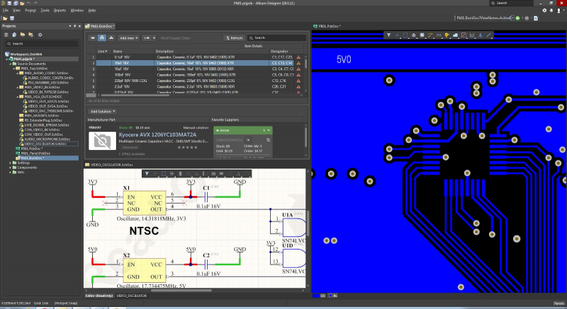
Power supply components need to be carefully chosen to ensure electrical function and reliability. Your power supply components can be selected in your PCB design software when you have instant access to the electronics supply chain through your component libraries. Altium Designer gives you this access to the electronics supply chain through the Manufacturer Part Search panel, where you can search for components by manufacturer, part number, or specification. You can then instantly add these parts to your BOM and start placing them in your design.
Integrated Schematic Capture for Your Power Supply Circuits
Don’t resort to padding out your design tools with external simulation tools. You can use the SPICE engine in Altium Designer to simulate power distribution in your regulator circuits, and you can visualize important transient analysis results for the power output in your design. After fully evaluating the electrical behavior in your power supply circuits, you can use an integrated schematic capture tool to start your PCB layout. Only Altium Designer can guide you through the entire power supply design process without any external design and simulation programs.

Altium Designer includes everything needed to ensure safety and compliance with industry standards.
Altium Designer is the industry’s premier design software for power supplies, embedded systems, RF products, mobile devices, high speed computer systems, and much more. When you use Altium Designer, you’ll have access to every tool you’ll need for power supply design in a user-friendly interface.
The major advantage of Altium Designer over other ECAD applications is its integrated toolset. Everything needed to design power electronics and PCBs for other advanced electronics is included in a single application. Best of all, you’ll stay productive thanks to the underlying rules-driven design engine and streamlined user interface.
Stay Productive With Rules-Driven PCB Design Software
All of the PCB design features in Altium Designer were built to work together and to help ensure your board complies with important industry standards. Any functionality and safety standards that are important for your design can be defined as design rules, and your design will be checked against your design rules as you create your board. No other PCB design application helps you stay this productive and build highly efficient power supply designs.

Build and simulate a power supply filter for advanced power converters in Altium Designer.
Altium Designer gives you access to a full suite of PCB design tools that help you create highly efficient and safe power supply designs. Forget about using multiple programs for design, layout, and simulation, use the industry’s best set of PCB design tools in a powerful application.
Altium Designer on Altium 365 delivers an unprecedented amount of integration to the electronics industry until now relegated to the world of software development, allowing designers to work from home and reach unprecedented levels of efficiency.
We have only scratched the surface of what is possible to do with Altium Designer on Altium 365. You can check the product page for a more in-depth feature description or one of the On-Demand Webinars.


