Power Supply Design in Altium Designer
Whether you’re designing a bench power supply for an electronics lab, or you need to design an embedded power supply for an IoT product, you’ll need some world-class PCB design tools. Altium is here to help you floorplan your power supply and create a set of detailed schematics with powerful circuit design and simulation features. With the schematic design features in Altium Designer, you can create and simulate your new power supply design. You’ll also have the features you need to source components and prepare your new power supply for manufacturing. No other PCB design platform gives you this many features for success.
ALTIUM DESIGNER
A professional PCB design software platform that integrates circuit design features with a powerful PCB editor and simulation features for power supply design.
Every circuit board needs a power supply. Your power supply design strategy can involve integrated circuits when working with low level signals, but higher power designs need discrete components to provide the required power output and regulation. Whether you’re creating a simple regulator using multiple converters and an LDO, or you’re designing for high current output, you’ll need a powerful schematic editor to create your power supply circuit. Take a look at our comprehensive power supply design guide to see how you can use the design tools in Altium Designer for your new board.
Planning Your Power Supply Design
Your power supply and regulation strategy involves several stages, and it requires considering your input power source when planning your new design. AC-AC conversion is quite simple and only involves step-up or step-down regulation, possibly with a power correction factor circuit to increase efficiency. If you’re planning a power supply for AC-DC conversion, your power supply design will be similar to the block diagram below.

AC-DC power supply design block diagram.
Once you’ve converted your AC input to DC, you can follow the typical DC-DC conversion and regulation strategy to output stable DC voltage at the desired current. DC-DC conversion requires implementing the right power supply topology. The most common topologies are buck, boost, and buck-boost conversion, but related power supply topologies can be used for DC-DC conversion and regulation. Note that the flowchart shown below is also used with unregulated DC power sources to generate stable DC power for your components.

DC-DC power supply design block diagram.
Each stage in the regulator needs to be built from discrete components and/or integrated circuits that provide each function. You can create a power supply from passives and power regulator ICs, or you can use discrete components. Different stages can be isolated to prevent a high voltage from reaching the output port, which eliminates an important safety hazard. Once you’ve determined your power conversion and regulation strategy, you need to choose your components and create schematics.
Schematic Design for a New Power Supply
The conversion and regulation stages shown above are well-known and are available as reference designs from a number of manufacturers. You can also find many examples of different regulator and converter designs on Altium’s PCB Design blog. The schematic editor in Altium Designer allows you to find the components you need for your board with the Manufacturer Part search panel. These components will have verified schematic symbols, PCB footprints, and 3D models, as well as current sourcing information with updated quantities and prices.
- When you’re building a new switching regulator, you need to design and simulate all aspects of your new device with the best schematic editor.
- Your DC-DC conversion and regulation stages require selecting the right topology for your new power supply design. Learn more about DC-DC converter topologies.
- You can find the components you need for each conversion and regulation stage in your power supply design with the Manufacturer Part Search panel in Altium Designer.
Learn more about the Manufacturer Part Search panel in Altium Designer.

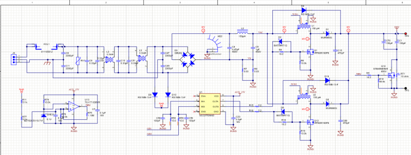
Rectifier, EMI filter, PFC, and buck converter sections of a power supply design in Altium Designer
Designing Each Regulator Stage
When selecting components for your power supply design, pay close attention to important specifications in datasheets. Input and output voltage/current levels are quite important, but you also need to consider other components for regulation. If your input power source will vary during operation, you’ll need to have a strategy to ensure the output from your power supply remains stable during operation. This is perhaps the most important point in designing a power supply to accommodate different input power sources.
Your regulator stages may need to have feedback with a regulator controller IC, which then uses a PWM signal to ensure the output from your regulator is maintained at the desired voltage. The idea is to maintain the regulator stage output above the dropout voltage for the final LDO (see above), or to set the regulator output at a specific value. Controller ICs are available for these tasks, and they can be easily added to a regulator design in the feedback loop.
Evaluating Your Power Supply Design with Simulations
Once you cascade your regulator stages and determine how your input power signal will behave, you’ll need to verify the functionality of your design before you create your layout. This is the best time to examine your power supply design with a SPICE-based simulator. When your schematic editor includes an integrated simulation tool, you’ll be able to instantly run DC and mixed-signal simulations directly from your schematic data. Once you’ve evaluated your design, you can use an integrated schematic capture tool to start your power supply layout.
- Working with a circuit simulator directly in your schematic editor allows you to instantly evaluate your new power supply design and determine that your circuits will operate correctly.
Learn more about using a schematic editor with an integrated SPICE simulator.
- Regulator stages in a power supply can be isolated or non-isolated. An isolated power supply is safer as it prevents high voltage shock from reaching the output.
- Schematic capture is the first step involved in creating a PCB layout for your power supply design.
Learn more about creating a PCB layout from a schematic using schematic capture.

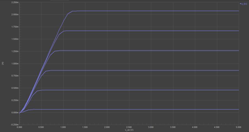
MOSFET simulation outputs generated from the schematic editor in Altium Designer
The Best ECAD Software for Power Supply Design
From the schematic editor to the powerful CAD tools, Altium Designer has everything you need for power supply design. The schematic editor includes a circuit simulator for evaluating circuit functionality, and the PCB editor allows you to instantly import your schematic into a new layout. You’ll remain at your most productive when you use Altium Designer.
Complete Your Entire PCB Design in Altium Designer
Although the schematic design and circuit simulation features in Altium Designer are ideal for power supply design, you won’t be limited to build regulators and converters. The schematic and layout design features in Altium Designer can be used to create powerful new products in any application. From high speed/high frequency design to power distribution systems, you’ll have a complete set of tools for all aspects of electronics design.
Altium Designer is also the only platform that gives you the features you need to prepare a board for full-scale manufacturing. Altium Designer makes this process easy by integrating all your design data in a single location. You won’t have to use separate programs to create bills of materials, Gerber files, drill files, or assembly drawings. You can prepare everything you need for prototyping and full-scale manufacturing in Altium Designer.
- Schematic creation, simulation, and layout for power supply design are unbelievably easy in Altium Designer. The rules-driven design engine in Altium Designer brings all your design features into a single program. Learn more about the integrated design environment in Altium Designer.
- Once you create your PCB layout, you can examine power distribution throughout your PCB with Altium Designer’s PDN Analyzer. You can locate hot spots in your board and correct your layout to eliminate them quickly and easily. Learn more about the PDN Analyzer in Altium Designer.
- When you’re ready to produce boards for your new power supply design, you can instantly send your project release to your manufacturer when you add Altium Concord Pro to Altium Designer. Learn more about adding Altium Concord Pro to Altium Designer.
Power supply design in an integrated environment helps you stay productive and create higher quality products. If you’re just getting started using an integrated PCB design environment, Altium gives you the resources you need to design successfully. You’ll have access to the AltiumLive forum, webinars and podcasts with industry experts, a huge knowledge base with plenty of design tips, and design tutorials. No other PCB design software company is this invested in your success.
Altium Designer has set a new standard in circuit design, PCB layout, and simulation. You can implement the power supply design guidelines presented here and create other powerful products when you use Altium Designer.
Altium Designer on Altium 365 delivers an unprecedented amount of integration to the electronics industry until now relegated to the world of software development, allowing designers to work from home and reach unprecedented levels of efficiency.
We have only scratched the surface of what is possible to do with Altium Designer on Altium 365. You can check the product page for a more in-depth feature description or one of the On-Demand Webinars.
