EMI Case History — Noise Problems and Their Solutions — Part 2

In Part 1 of this article, I described an EMI noise problem occurring in a LCD touch screen display of an autonomous robot cleaning machine. In order to provide consulting services we needed to solve a problem which originated because of the ground and supply bounce in the leads of the IC devices that were incorporated into that display.
In Part 1, I also described the type of equipment in which the operation problem arose, the origin of the problem and the measurements that were taken to determine the scope of the problem. Here, in Part 2, I will describe the various solutions that were considered and the final fix that was implemented.
Researching the Various EMI Noise Solutions
As noted previously, discrete capacitors were not a viable option as the noise problem was beyond their scope of controlling it. As a result three different options were researched as a solution. They included:
- Changing the stackup and adding a plane capacitor.
- Changing to a lower inductance microcontroller.
- Using differential signaling for the LCD display interface.
- This was picked as the final solution.
The merits and drawbacks of the first two options and the selection of the third option are described below.
Changing the Stackup and Adding a Plane Capacitor
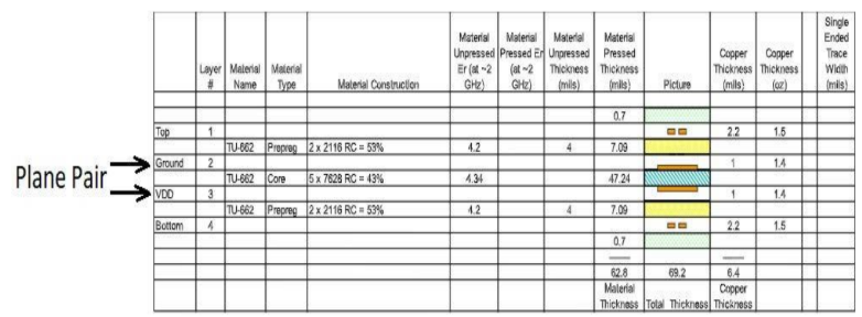
There was high-frequency noise (above 100Mhz) in the EMI receiver response. The controller PCB of the LCD unit was designed with a four-layer stackup as follows:
- There was one internal plane as ground.
- There was one internal plane as +3.3V (VDD).
As depicted in Figure 1, the aforementioned plane pair was separated by 47+ mils of dielectric. Both of the planes had signal traces embedded in them which compromised their integrity. The goal was to reduce the effect of the high edge rates as well as to correct the layout of the PCB which was poorly done.
As has been described in Reference 1 at the end of this article, plane capacitance can reduce the EMI problems by filtering EMI noise at the PCB level. That plane capacitance in a PCB is calculated (in farads) as shown in Equation 1.

Where: εo is permittivity of free space and εr is the permittivity of the dielectric, A is the overlapping area of the plane layers, and d is the dielectric thickness between the planes in the stackup.
Equation 1. Equation for Calculating Plane Capacitance in a PCB
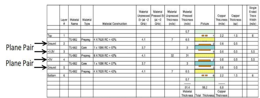
The original PCBA of the LCD unit had ~47mils dielectric between the power and ground plane. This was not adequate to filter out any of the high-frequency EMI noise. As a result, the LCD PCB was redesigned by adding more plane capacitors into the layer stackup. This is shown in Figure 2. This new stackup depicts the following:
- The dielectric thickness between the 3.3V and Ground was reduced to 3mil.
- An additional plane capacitor was added for the 5V rail as some logic circuits in the driver PCBA also used 5V.
- The power and ground planes were also designed without any traces passing through them.
- For all ICs in the design, power, and ground nets connected directly to the respective planes ensuring the lowest line impedances possible.
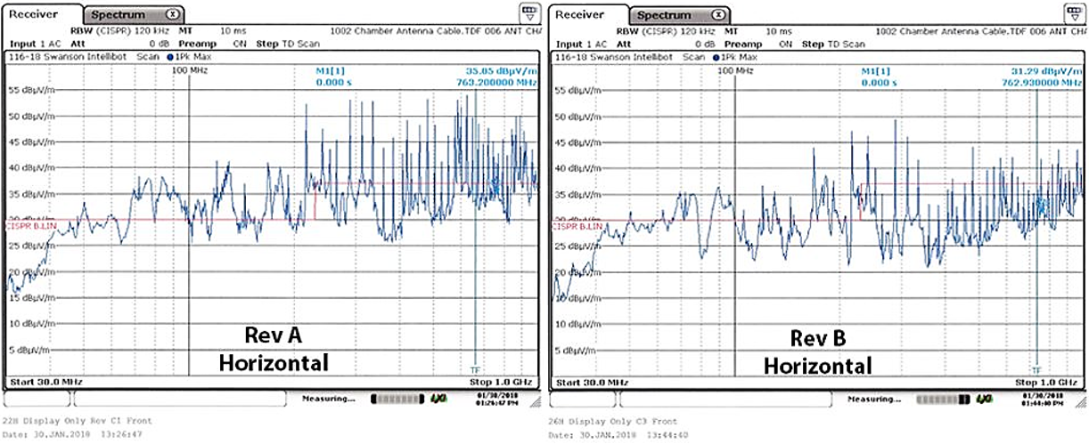
The EMI receiver response for the new revision of PCBA, Rev B shows significant improvements compared to Rev A as can be seen in Figure 3. By adding plane capacitors to the PCB stackup, there was a ~10dB to ~20dB EMI noise reduction in the 200MHz to 1GHz range. Unfortunately, after implementing the PDN filter solution it was discovered that it would never be possible to mitigate all of the EMI noise created by the ground bounce from the LCD display. This was due to the fundamental limitation of the inherent inductance of the return paths within the microcontroller package available. As noted in other articles, any problem that is IC-package related cannot be remedied by any actions taken on the PCB. This is because the inductance in the ground lead is not the only inductance in the package. All of the output pins also have an associated inductance. It was determined that a better approach was to reduce the inductance in all the leads of the IC package. Therefore, the design needed to be updated with a lower parasitic lead inductance package such as that found in a BGA.
Changing to a Lower Inductance Microcontroller
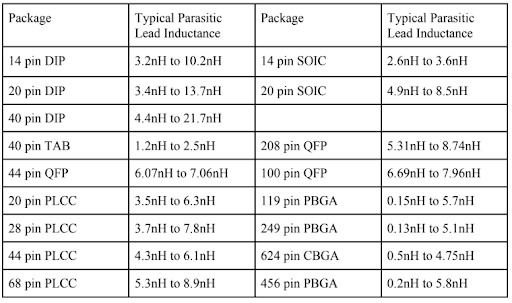
Per the above, the next step was to research a variety of IC packages to learn more about the typical parasitic inductances associated with each one. The lead inductances of a variety of IC packages are provided in table 1.
Voltage across an inductor as a function of time is provided in Equation 1. In this instance, the edge rate can be substituted for time.

Where: VL is the voltage in volts across the inductor, L is the inductance in Henrys, dI is the change in current, and dt is the change in time.
As edge rate increases (dt decreases), VL goes up and points in the opposite direction. With die shrinks, both dI and edge rate (dt) cause an increase in VL, which, in turn, can cause large voltage transients in the power supply leads. For a 208 pin QFP package with max lead inductance = 8.74 nH, assuming dI = 20 mA and dt = 2 ns, for a single-switching IO line switching (1 bit), the voltage across the inductance from the die including the wire bond and the pin is 87 mV. If 10 bits of the IC are changing simultaneously the voltage across the inductor is 870 mV.
The STM32F4 used in the LCD driver PCBA was using a 176 pin LQFP package with an inductance in the range of 7 nH to 10 nH per pin. As was delineated in Part 1 of this article, the ground bounce measured on the STM32F4 MCU was ~780 mV. The STM32F4 datasheet specified dI = 5 mA max per IO line. Thus the inductance per pin from the measured ground bounce value could be calculated. Ideally, the intent was to find a correlation to the measurement if the calculated inductance was close to the inductance numbers that were specified in the datasheet. Assuming dt = 1 ns, using dI = 5 mA and VL equaling 780 mV, the total package inductance was calculated to be 176 nH.
Next, the inductance per pin was approximated by dividing by 24 bits active during the 780 mV measurement noted above.
This correlated to the ~7 nH of 176 pin LQFP package with 24 bits switching for the RGB LCD interface. Unfortunately, in this instance, the LCD manufacturer was not ready to change the IC package. So other solutions had to be considered.
Using Differential Signaling for the Display Interface
As an alternative to the parallel RGB interface originally used, the option was to use a differential signaling interface to the display. Because the logic state changes in the differential circuit are opposite of each other the current that flows from the power supply remains steady. This is one of the more significant advantages of differential signaling over single-ended signaling. Because the magnitude of current flowing through the power leads of the IC package remains constant, there is zero supply and ground bounce of simultaneous switching noise (SSN) across the inductance in the power leads.
As a result of the foregoing, the robotic system was updated with a new LCD display that used a differential signaling interface. A Renesas Synergy microcontroller, with a 176 pin LQFP package (with typical parasitic inductance of ~7nH to 10nH) was used in the LCD driver PCBA. Figure 4 depicts the EMI response of the new LCD display against the original LCD display Rev A that had the ground bounce.
The LCD Rev A with supply and ground bounce showed multiple noise peaks crossing the CISPR Class B limit (this is the red line in Figure 4). The new LCD display, with differential signals, showed only a few noise peaks were crossing the CISPR Class B limit (shown by the lower red line in Figure 4). There was a ~20dB improvement over the original LCD display Rev A version. With the updated LCD display, the EMI emission peaks were well within the CISPR Class A limit (this is depicted by the upper red line in the image in Figure 4 on the right).
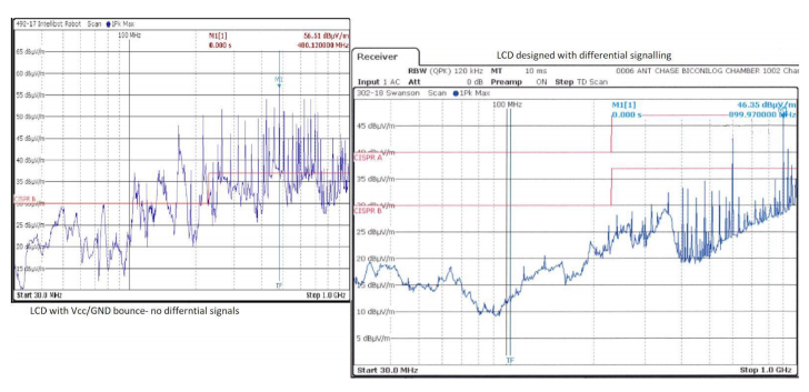
The foregoing demonstrates why differential signaling is a very good way to reduce EMI noise that is generated from supply and ground bounce. It’s true that the two wires, two connector pins, two drivers and two receivers required for differential signaling added extra cost to the design but that cost was small compared to having a major piece of equipment that was not functional.
Summary
Now we have a clear understanding of how EMI noise resulting from the ground and supply bounce created by the ICs at the device level can be readily propagated to the PCB onto which those ICs are mounted as well as the system itself. While some benefit can be gained by adding more plane capacitance to the PCB or switching to a lower inductance microcontroller, the inductance that is inherent in the leads of any IC device can be of such a magnitude that additional steps need to be taken. Switching from single-ended signaling to differential signaling can provide a solution that adds a bit more cost to the overall design but ensures that the final product will operate as designed.
Talk to an Altium expert today to learn more or discover more about the best high-speed design tools in Altium Designer®.
References
- Ritchey, Lee W. and Zasio, John J., “Right The First Time, A Practical Handbook on High-Speed PCB and System Design, Volume 1.” 2. Krishnan, Sunumani and Dannan, Benjamin, “How Ground Bounce Can Ruin Your Day,” Presented at DesignCon 2020.