Antipad Diameter, Crosstalk, and IBM’s Results from IPC APEX EXPO 2021

These days, you probably don’t think of IBM as a major force in the PCB industry. IBM has made a big push into cloud and has not received much love from the electronics industry. However, the company known for their mainframes, servers, Watson, and AI capabilities is making waves in the high-speed design community with their recent results presented at IPC APEX 2021.
The paper presented by a team of three IBM researchers looks at ways to reduce interlayer crosstalk in high-density designs with back-drilled PTH vias. The paper is quite interesting as it examined two aspects of back-drilled PTH via design that one might not intuitively link to reducing crosstalk. However, in high density design with very low spacing between high speed interconnects, we have to look just about everywhere to try and reduce signal integrity problems, including crosstalk.
Their results are very interesting when we look at antipads and their effects on signal integrity. With this in mind, let’s look at these interesting results and explore how they might affect your design practices going forward.
What is Interlayer Crosstalk?
Before getting into the meat of IBM’s paper, it’s important to define interlayer crosstalk in a high speed PCB. You might be wondering, why would crosstalk occur between two layers in a high speed PCB? Don’t we normally place a ground plane between signal layers on a high-speed PCB to prevent any crosstalk between layers? While it’s true that ground planes between signal layers provide isolation, it’s sometimes tough to place a ground plane between every possible pair of signal layers. With high layer count designs that must also support dense routing of high speed signals, you don’t always have the luxury of placing ground planes between every signal layer.
Enter interlayer crosstalk. When traces are placed on adjacent layers, there is the potential for crosstalk between traces due to coupling between the conductors. This includes crosstalk between controlled impedance broadside coupled traces on adjacent layers. A typical recommendation with controlled impedance traces is to route them orthogonally as this would eliminate inductive crosstalk, although this is not always practical in terms of routing solvability.
Broadside-Edge Coupling
Personally, I shy away from orthogonal routing on striplines and just opt for separation laterally (edge coupling) or on different layers. In very high density designs, where you are forced to use striplines on adjacent layers, you have broadside or broadside-edge coupling between traces. This occurs in single-ended traces and in differential pairs; note that you’ll be dealing with differential pairs in high speed digital routing.

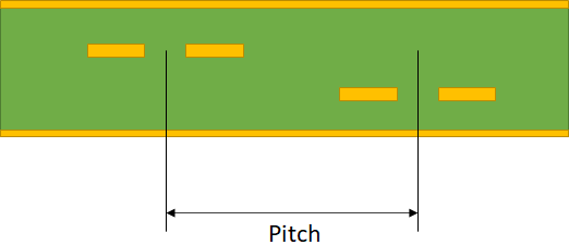
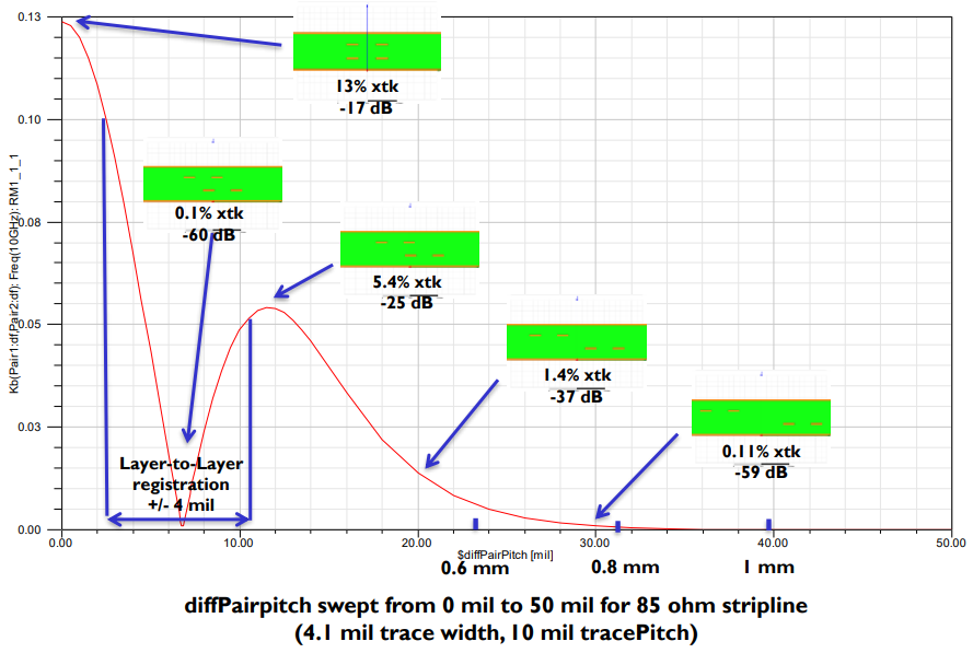
With broadside-edge coupled differential pairs, there is a specific pitch between pairs on the adjacent layers that produces zero reverse interlayer crosstalk. In truth the crosstalk strength is not perfectly zero, but you can certainly get the crosstalk strength below -60 dB. In differential pairs, this occurs because the field from the aggressor pair will be perfectly parallel to the cross-section of the victim pair, leading to zero inductive interlayer differential crosstalk, according to Faraday’s law.
Misregistration
Due to manufacturing tolerances, the pitch between your differential pairs will not be perfectly equal to the design value, and there will be some misalignment between layers. This is called misregistration and it leads to some small amount of crosstalk occurring in the victim pair. This misregistration can be as high as 5 mils, which is one value that was investigated in IBM’s study.
Scott McMorrow of Samtec has an excellent presentation that shows the effects of misalignment between differential pairs on interlayer crosstalk. I’ve presented an important result from his presentation below as this nicely shows how inter-pair pitch affects forward crosstalk.

The Results in IBM’s Paper
Now we can get into IBM’s work on interlayer crosstalk. They looked at interlayer crosstalk from two dimensions: layer misregistration and antipad diameters on PTH vias. We would naturally expect that misregistration reduction has the biggest effect on interlayer crosstalk, but as it turns out, adjusting the antipad diameter had a greater effect on reducing interlayer crosstalk than reducing misregistration.
Without repeating all the results from their paper, I’ll briefly summarize the important signal integrity results:
Interlayer Crosstalk and Reliability vs. Misregistration
When misregistration was reduced from 5 mil down to 3 mil, the interlayer crosstalk strength on the victim lines decreased, which is consistent with the results from McMorrow shown above. What’s important about this result is that it is universal: tighter tolerances lead to smaller misregistration and lower crosstalk throughout the PCB layout.
The more surprising result the team found was the effect of a changing antipad diameter on the same type of crosstalk.
Antipad Diameter
For traces making layer transitions over back-drilled PTH vias, the antipad diameter was found to also affect interlayer crosstalk between coupled interconnects. The antipad around a through-hole via is already known to modify the parasitics around the via and the nearby trace, creating a slight impedance mismatch that accumulates loss. In the IBM paper, reducing the antipad diameter from 30 mils to 28 mils on a 10 mil diameter PTH also produced a reduction in interlayer crosstalk. This is one example of a simple design change that will help you reduce crosstalk, but it relies on exacting tolerances around a PTH with precise backdrilling, something that not all fabricators might be able to accommodate.
Summary
The results shown in IBM’s paper are important because they illustrate the link between an important signal integrity problem and manufacturing tolerance at small length scales. As advanced designs continue to get more compact, more of these investigations will help reveal the influence of manufacturing tolerances on signal and power integrity. Interlayer crosstalk is not a new problem to be solved. A good review and some alternative routing strategies for reducing interlayer crosstalk in dual striplines can be found in the following 2013 paper:
Here at Altium, our goal is to keep you updated on the latest developments in interconnect design, including aspects like antipads, crosstalk, and signal integrity in high speed designs. As the electronics industry continues pushing the boundaries of electronics packaging, you’ll have all the tools you need to build the highest quality designs with Altium Designer® and the Altium 365™ platform. Keep watching the blog for more engineering and technology updates.
